Chambered ion reflux system for ion chromatography, apparatus and method of use

Inactive Publication Date: 2017-07-27
RIVIELLO JOHN M
View PDF5 Cites 3 Cited by
  • Summary
  • Abstract
  • Description
  • Claims
  • Application Information

AI Technical Summary

Benefits of technology

The present invention is a chambered ion reflux device for ion chromatography that includes an eluent generation chamber, an electrode chamber, a suppressor chamber, and a barrier to prevent liquid flow. The device also includes an ion removal chamber. The method involves flowing deionized water through the eluent generation chamber to generate an eluent, neutralizing the eluent with a suppression chamber, and then flowing the neutralized eluent through the ion removal chamber and the barrier to prevent liquid flow. The device and method allow for efficient and effective ion chromatography.

Problems solved by technology

These gases can compromise the performance of the system by causing pump flow irregularity and interfering with conductivity detection.
In addition, electrochemical by-products of electrolysis such as hydrogen peroxide and ozone can cause chemical degradation of critical components, such as the separator in the chromatographic system.

Method used


Image

  • Chambered ion reflux system for ion chromatography, apparatus and method of use
  • Chambered ion reflux system for ion chromatography, apparatus and method of use
  • Chambered ion reflux system for ion chromatography, apparatus and method of use

Examples


examples

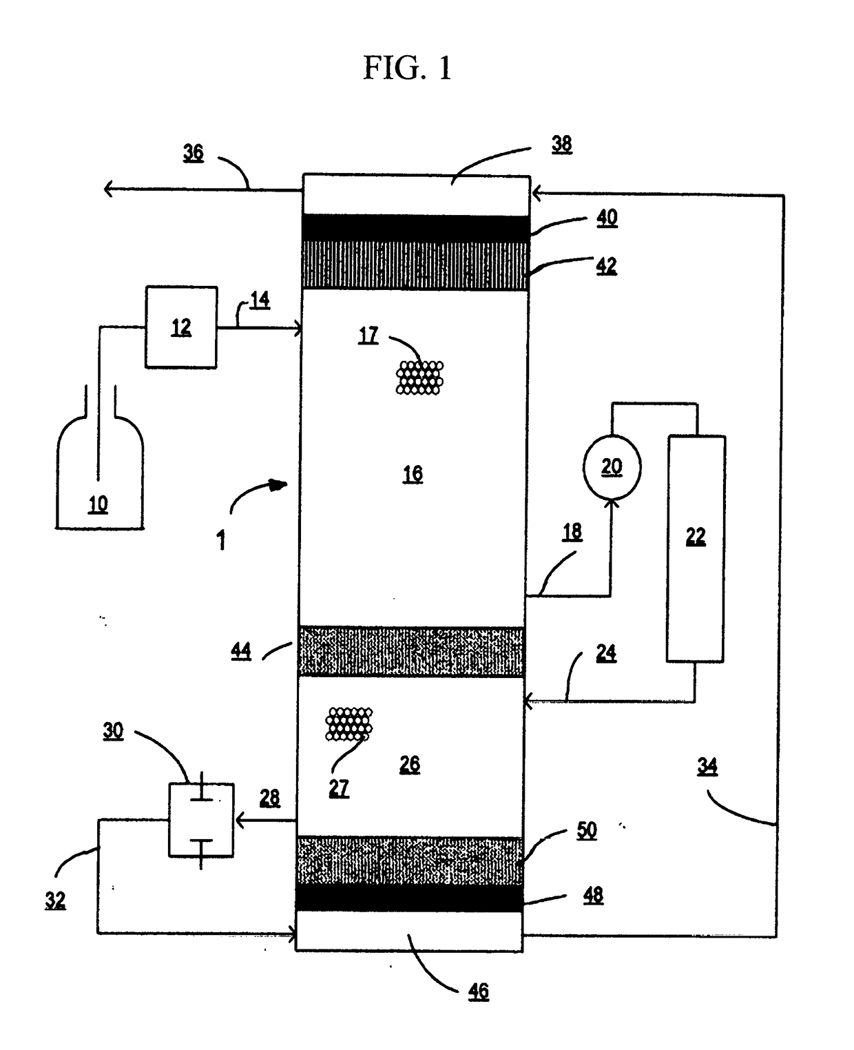
[0040]A chambered ion reflux device for anion IC as depicted in FIG. 1 was constructed using machined poly etheretherketone (PEEK) hardware to retain the electrodes, membranes and resin. The internal flow dimensions of the suppression chamber were 0.40 cm in diameter and 1.3 cm in length. The suppressor chamber volume was approximately 160 μL. The internal flow dimensions of the eluent generation chamber were 0.80 cm in diameter and 3.8 cm in length with an internal volume of 1900 μL.

[0041]The anode chamber contained a platinum foil electrode. In contact with the anode and separating the anode chamber from the suppression chamber was a cation exchange membrane stack (Electropure Excellion I-100 cation exchange membrane, a product of Electropure Inc, Laguna Hills, Calif.). A portion of the suppression chamber closest to the anode chamber was filled with cation exchange resin (DOWEX™ 50x4 (100-200 mesh), a product of the Dow Chemical Company, Midland, Mich.) in the hydronium form. The...


PUM

PropertyMeasurementUnit
Electric chargeaaaaaaaaaa
Currentaaaaaaaaaa
Transport propertiesaaaaaaaaaa

Abstract

A chambered ion reflux device for ion chromatography which electrolytically produces an eluent from a water pumped phase, suppresses the eluent and recovers (refluxes) the eluent ions for reuse. In the chambered ion reflux device, the eluent never passes through the electrode chambers. Since the eluent ions are refluxed and the eluent is produced electrolytically, the chambered ion reflux device can be used for isocratic or gradient ion chromatography. A chambered ion reflux device which integrates an electrolytic ion removal chamber is also disclosed.

Description

BACKGROUND OF THE INVENTION[0001]Electrolytic ion exchange devices have been used in Ion Chromatography (IC) for more than 35 years. The first electrolytic devices were suppressors which served to reduce the background conductivity of the eluent, while at the same time increasing the conductivity of the analytes being measured. Such suppressors are described in U.S. Pat. No. 4,459,357, U.S. Pat. No. 5,248,426 and U.S. Pat. No. 5,633,171. Just as electrolytic suppressors can be used to remove eluent ions, devices referred to as eluent generators can be used to electrolytically add ions to water for the production of an acid or base eluent. Electrolytic eluent generators have also been developed and allow the production of eluent using water as the pumped phase as described in U.S. Pat. No. 6,955,922. In these eluent generators, a large reservoir of the eluent ion is separated from the flow through generator chamber by an ion exchange barrier. The eluent ion reservoir and the generato...

Claims


Application Information

Patent Timeline
IPC IPC(8): G01N30/96B01D15/16B01D15/36
CPCG01N30/96B01D15/166B01D15/361B01D15/36B01D15/22
Inventor RIVIELLO, JOHN M.
Owner RIVIELLO JOHN M
Why Eureka
Try Eureka