Device for modification of ejected casings trajectories

Active Publication Date: 2016-06-23
HAYES WILLIAM DONALD
View PDF30 Cites 1 Cited by
  • Summary
  • Abstract
  • Description
  • Claims
  • Application Information

AI Technical Summary

Benefits of technology

[0014]An advantage of an embodiment is to modify and control the speed and trajectory of the spent casing through the deflection and dampening of the spent casing by contact with the device after the spent casing is ejected from the firearm. Through controlled deflection and dampening, the spent casings would be collected in a small area close to the firearm. This further aids in the collection and clean-up after continuous operation of the firearm. This further aids in the recycling and reuse of the spent casing, thus effecting savings to costs and materials.
[0015]Another advantage of an embodiment is to facilitate the operation of the firearm from a number of various user positions for operating the firearm. Through controlled deflection, the spent casings can be deflected to a suitable area away from the user of the firearm at various operating positions. Through controlled dampening, the ejection of the spent casings can also be da

Problems solved by technology

There are deficiencies with the related art.
The brass deflectors on the AR platform and other types of firearms are generally very erratic in their operation.
It is hard to control the deflection angles of each ejected casings as the firearm is in continuous operation.
Even slight variations in the casing's ejection speed and trajectory may lead to a large difference in the eventual displacement of the spent casing by the brass deflector due to the large comparative distance that ejected casing is eventually at rest (e.g., a few feet from the firearm).
Another deficiency is that the firearm with the brass deflector in the related art may be designed mainly to deflect the spent casings from a user operating the firearm at a typical right-handed firing position (e.g., aligning the aim of the firearm using the right eye and operating the trigger using the right hand, where the user's center of the body may be aligned with the left side of the firearm).
This

Method used


Image

  • Device for modification of ejected casings trajectories
  • Device for modification of ejected casings trajectories
  • Device for modification of ejected casings trajectories

Examples


Example

[0032]Reference will now be made in additional detail to an embodiment of the present invention, example of which is illustrated in the accompanying figures.

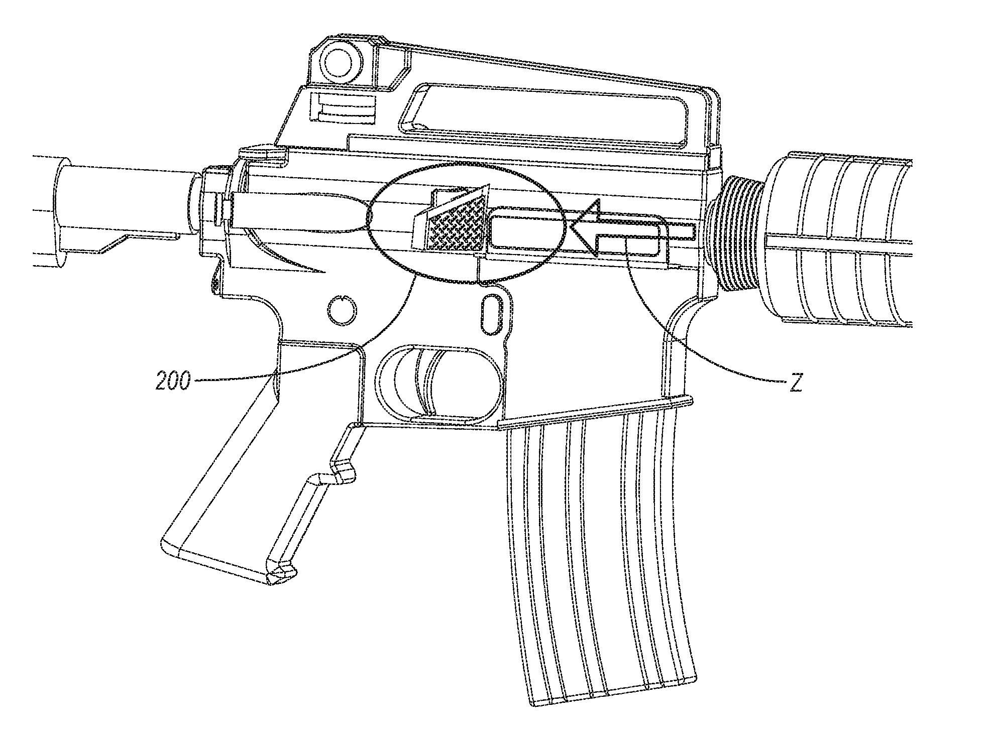
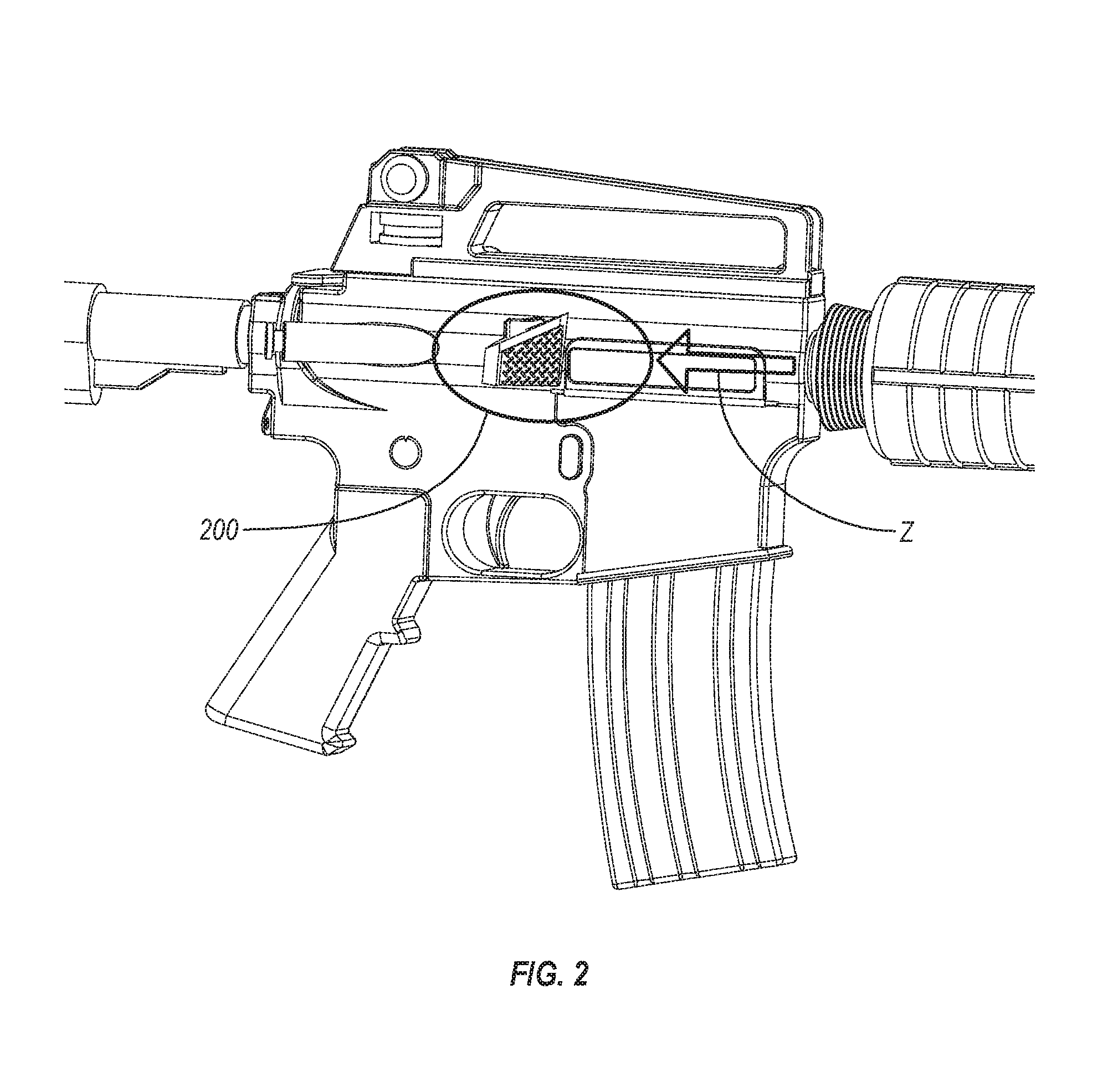
[0033]FIG. 2 illustrates views of a device for the modification of ejected casing trajectories attached to a firearm according to an embodiment.

[0034]Referring to FIG. 2, FIG. 2 illustrates a device for the modification of ejected casing trajectories 200 attached to the left side of the firearm (with the barrel and trigger as illustrated). Here, the spent casing after a use of the firearm would be ejected in from the firing chamber a trajectory Z to the left side and towards the front side of the firearm (e.g., towards the barrel). The device 200 may be attached to be in the expected trajectory A1 of the ejected casing on the left side of the firearm in front of the firing chamber. Here, the device 200 is illustrated as being attached to a pre-existing brass deflector of the firearm. However, in another embodiment, the device 20...


PUM


Abstract

A device for modification of ejected casings trajectories includes a top side and a bottom side. The bottom side is configured for attachment to a location on a firearm. The location is in an expected trajectory of spent casings ejected from the firearm. The top side includes a surface facing the expected trajectory of the spent casings. The surface is configured to modify a trajectory of the spent casings by accepting an impact at an angle with each spent casing at a point of impact on the surface and deflecting the spent casings at a deflection angle. The deflection angle is dependent on the point of impact. The surface may include an angled surface or a curved surface. One side of the curved or angled surface may be raised compared to another side of the curved or angled surface.

Description

CROSS REFERENCE TO RELATED APPLICATIONS[0001]This application claims the benefit of U.S. Provisional Application No. 62 / 095,565, filed Dec. 22, 2014, which is herein incorporated by reference.BACKGROUND OF THE INVENTION[0002]1. Field of the Invention[0003]The present invention generally relates to a device for modifying ejected casings trajectories, and more particularly to an apparatus, device, and method for deflecting and dampening spent casings ejected from the firing chamber of a firearm.[0004]2. Description of the Related Art[0005]Firearms include weapons in the various barreled weapons types where the firearm works to launch one or more projectiles through the barrel of a firearm when acted by a driving force. Modern firearms usually use an integrated cartridge that includes the projectile and the driving force as the ammunition.[0006]For example, FIG. 1 illustrates a cartridge 100 for a modern firearm. The projectile is the bullet 130 at the head of the cartridge 100. The dr...

Claims


Application Information

Patent Timeline
IPC IPC(8): F41A9/55
CPCF41A9/55F41A9/60
Inventor HAYES, WILLIAM DONALD
Owner HAYES WILLIAM DONALD
Why Eureka
Try Eureka