Virtual image display apparatus

a virtual image and display device technology, applied in the field of virtual image display devices, can solve the problems of obstructing the reduction in size and weight, affecting the display effect of external scenes, and affecting the display effect of external scenes, and achieve the effect of wide viewing angle and high performan

Active Publication Date: 2016-06-23
SEIKO EPSON CORP
View PDF3 Cites 19 Cited by
  • Summary
  • Abstract
  • Description
  • Claims
  • Application Information

AI Technical Summary

Benefits of technology

[0015]An advantage of some aspects of the invention is to provide a small and lightweight virtual image display apparatus which has a wide viewing angle and high performance.

Problems solved by technology

If the field of view of the observer is completely covered and thus only video light is viewed, an external scene is not noticed by the observer, causing uneasiness for the observer.
However, in case of the optical system of PTL 1, the projection lens is large in size, obstructing reduction in size and weight.
However, the optical system of PTL 2 has no consideration of displaying an external scene to the observer.
However, since video light is reflected by the half mirror surface twice, video becomes very dark.
However, in order to display an external scene by applying the optical system of PTL 3, it is necessary to attach a compensation lens to the outside of the concave mirror, resulting in an increase in thickness as a whole.
However, in case of the optical system of PTL 4, a convex portion at the center of the light guide member or a projection lens obstructs the field of view.

Method used


Image

  • Virtual image display apparatus
  • Virtual image display apparatus
  • Virtual image display apparatus

Examples


example 1

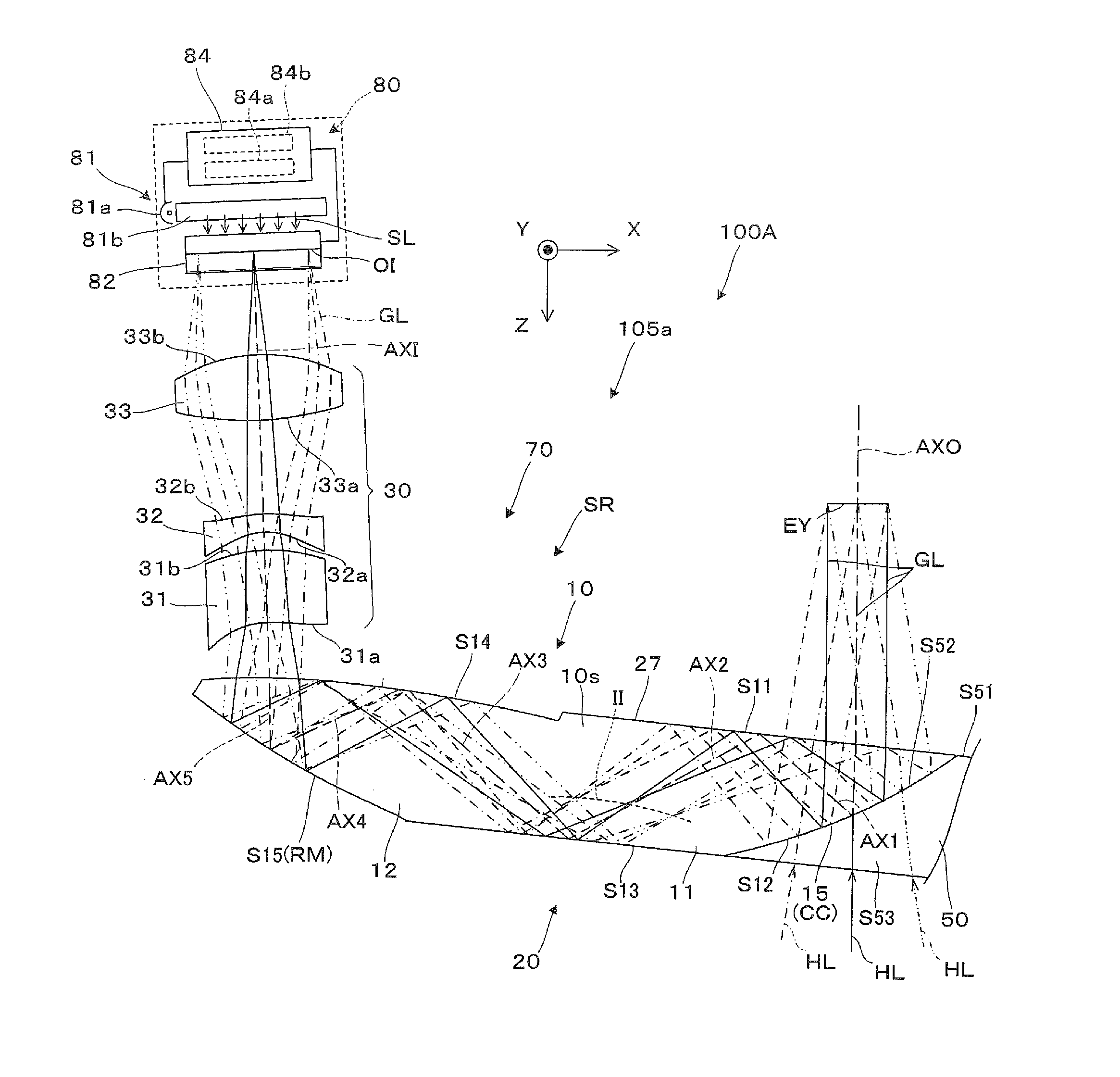
[0131]In a projection see-through device of Example 1, data on an optical surface constituting a light guide member and a projection lens (projection optical system) is shown in Table 1. Here, a light beam reversed with respect to the advancement of video light from the position of the eye is traced, and measurement is performed. For example, FFS1 means the first surface S11, FFS2 means the second surface S12, and FFS3 means the third surface S13. However, FFS6 means the lens surface 31a which is the emission surface of the first lens of the projection lens. ASP1 means the incidence surface of the first lens of the projection lens, not the emission surface, and ASP2 means the emission surface of the second lens.

TABLE 1NoTypeRTNdVd1SPH∞20.002FFS1—5.801.52555.953FFS2—−5.801.52555.954FFS1—10.461.52555.955FFS3—−22.701.52555.956FFS4—11.901.52555.957FFS5—−11.901.52555.958FFS4—−4.009FFS6—−6.001.52555.9510ASP112.481−1.5011ASP24.805−1.501.58529.9012ASP311.556−7.8613ASP4−21.429−5.501.52555.95...

example 2

[0138]In a projection see-through device of Example 2, data on an optical surface constituting a light guide member and a projection lens is shown in Table 5.

[0139]In a projection see-through device of Example 2, data on an optical surface constituting a light guide member and a projection lens (projection optical system) is shown in Table 5. FFS7 means the lens surface 31a which is the emission surface of the first lens of the projection lens. ASP1 means the incidence surface of the first lens of the projection lens, not the emission surface, and ASP2 means the emission surface of the second lens.

TABLE 5NoTypeRTNdVd1SPH∞20.002FFS1—4.801.52555.953FFS2—−4.801.52555.954FFS1—8.001.52555.955FFS3—−14.201.52555.956FFS4—8.701.52555.957FFS5—−7.001.52555.958FFS6—−2.009FFS7—−3.001.52555.9510ASP13.231−1.5011ASP22.180−1.501.58529.9012ASP34.010−7.1813ASP4−6.744−5.001.52555.9514ASP5−13.372−3.0015SPH∞−1.441.45867.8216image∞surface

[0140]In regards to the optical surface in the light guide member co...

example 3

[0145]In a projection see-through device of Example 3, data on an optical surface constituting a light guide member and a projection lens (projection optical system) is shown in Table 9. As shown in FIG. 12, in Example 3, the lens surface 32b which is the incidence surface of the second lens 32, not the first lens 31, in the projection lens 30 is a non-axisymmetric aspheric surface, and FFS6 means the lens surface 32b. For example, while ASP1 means the incidence surface of the first lens of the projection lens and ASP2 means the incidence surface of the first lens, ASP4 means the emission surface of the third lens, not the incidence surface of the second lens.

TABLE 9NoTypeRTNdVd1SPH∞20.002FFS1—5.501.52555.953FFS2—−5.501.52555.954FFS1—9.001.52555.955FFS3—−14.501.52555.956FFS4—9.501.52555.957FFS5—−9.501.52555.958FFS4—−2.009ASP1−7.938−5.001.52555.9510ASP26.561−1.0011ASP34.480−1.501.58529.9012FFS6—−6.1013ASP4−9.941−6.001.52555.9514ASP529.300−5.0015SPH∞−1.441.45867.8216image∞surface

[0146...


PUM


Abstract

A light guide member (10) includes three surfaces of a second surface (S12), a fourth surface (S14), and a fifth surface (S15) as two or more non-axisymmetric curved surfaces, and a projection lens (30) includes a lens surface (31a) as a non-axisymmetric aspheric surface. With this, on the light guide member side, even when there is a shape constraint that the first surface (S11) or the third surface (S13) which is a surface contributing to light guide is a flat surface, and correction of asymmetric aberration is limited, it becomes possible to perform sufficient aberration correction as the whole of an optical system including the projection lens. Therefore, the virtual image display apparatus can have a wide viewing angle and high performance, and can be made small and lightweight.

Description

TECHNICAL FIELD[0001]The present invention relates to a virtual image display apparatus which provides video formed by an image display element or the like to an observer, and in particular, to a virtual image display apparatus which is suitable for a head-mounted display mounted to the head of the observer.BACKGROUND ART[0002]Various optical systems have been proposed as an optical system which is assembled in a virtual image display apparatus, such as a head-mounted display (hereinafter, referred to as an HMD) mounted to the head of an observer (see PTLs 1 to 4).[0003]In regards to the virtual image display apparatus, such as an HMD, it is desirable to enlarge a viewing angle of video light and to reduce the size and weight. With the reduction in size and weight, it is possible to reduce the thickness in a visual axis direction of the observer and to bring the center of gravity close to the observer, thereby improving the fit.[0004]If the field of view of the observer is completel...

Claims


Application Information

Patent Timeline
Patent Type & Authority Applications(United States)
IPC IPC(8): G02B27/01G02B13/18G02B27/00G02B13/16
CPCG02B27/0172G02B13/16G02B13/18G02B2027/013G02B2027/0145G02B2027/0178G02B27/0012G02B17/0848G02B17/086G02B2027/011G02B2027/0123
Inventor KOMATSU, AKIRATOTANI, TAKAHIROTAKAGI, MASAYUKITAKEDA, TAKASHIMIYAO, TOSHIAKI
Owner SEIKO EPSON CORP
Why Eureka
Try Eureka