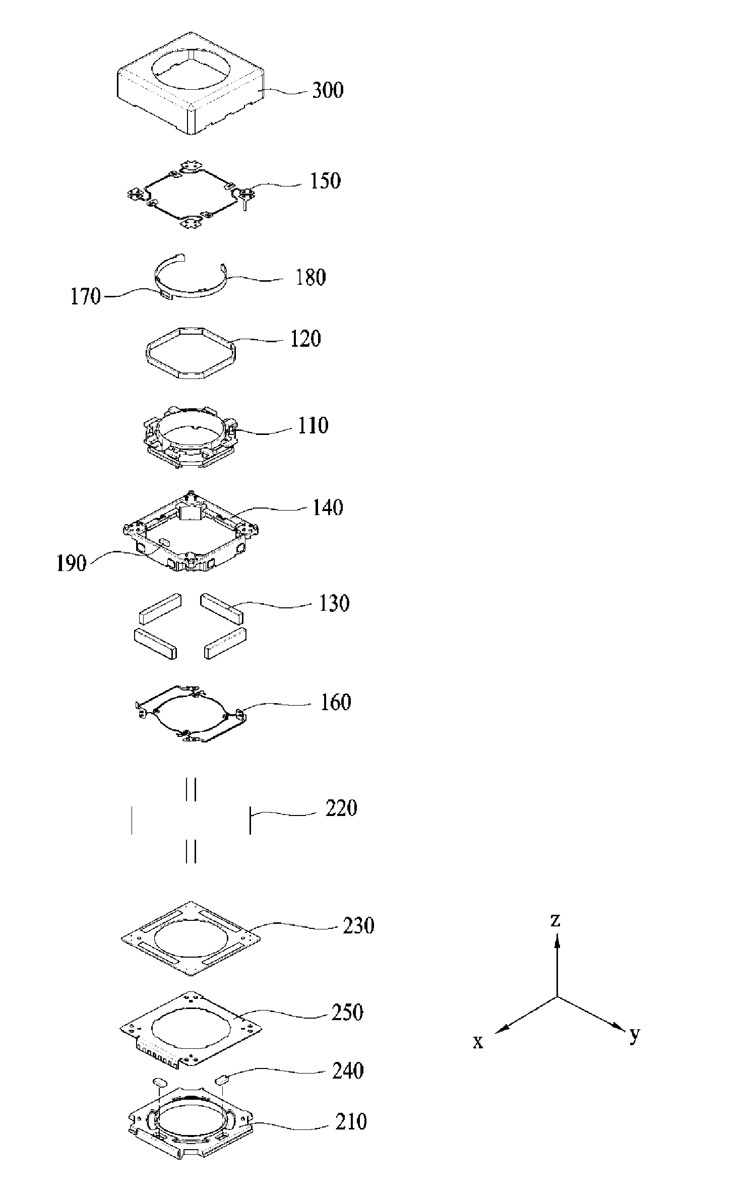
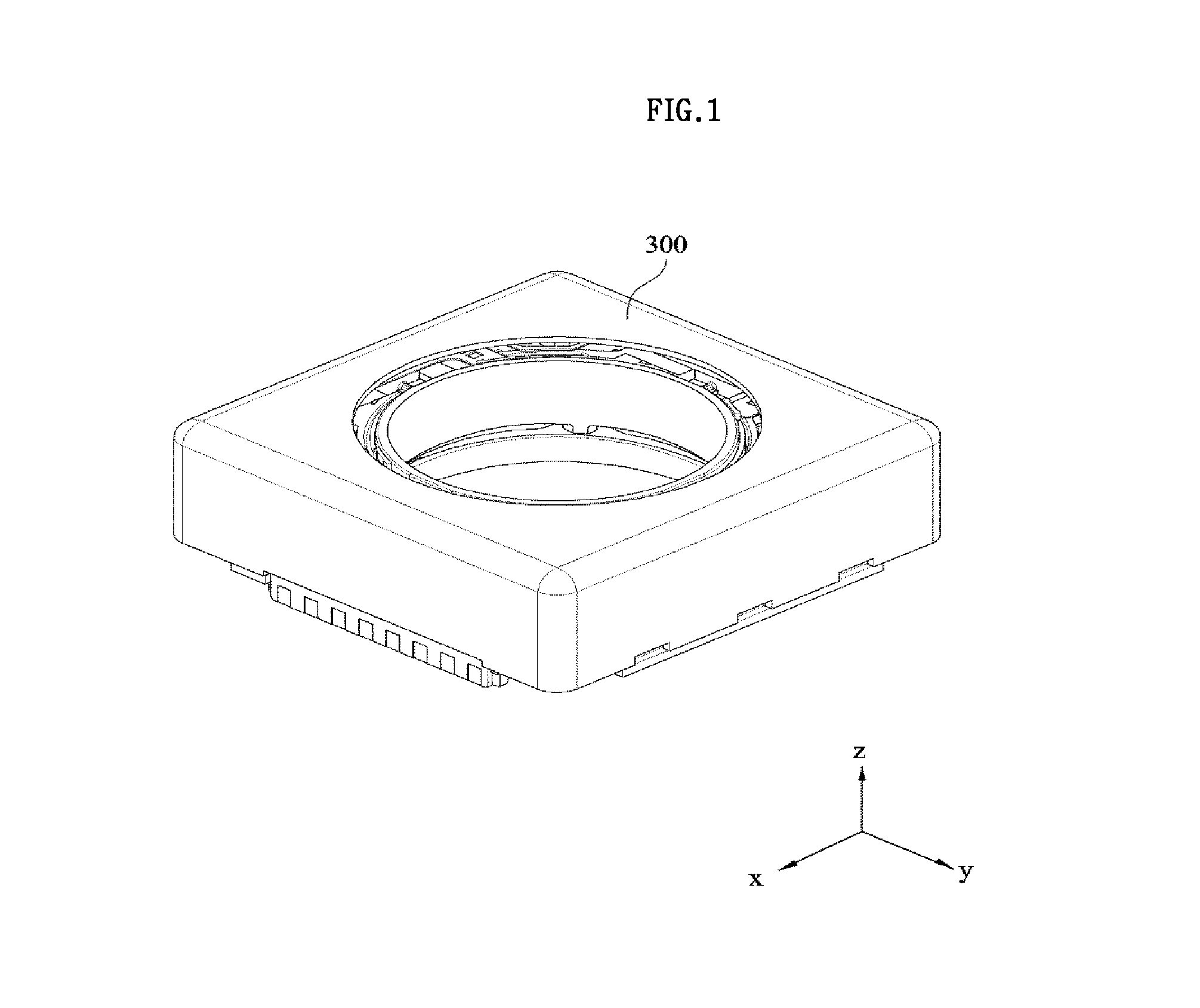
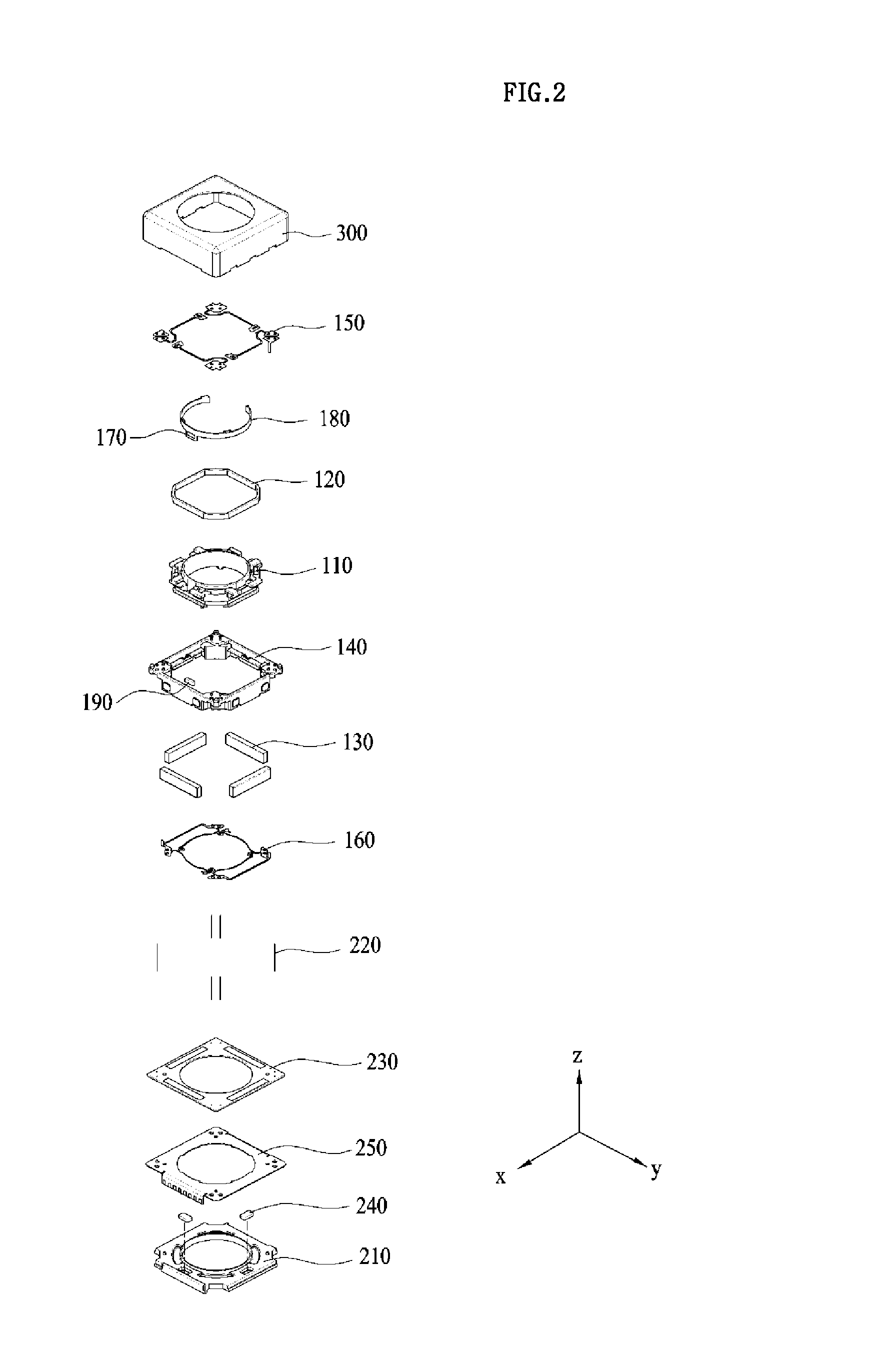
Lens Moving Apparatus
a technology of moving apparatus and moving rod, which is applied in the field of moving rod, can solve the problems of difficulty in applying voice coil motor, vcm, camera module may frequently receive shock, shake minutely, etc., and achieve the effects of improving the fixing ability of bobbins, reducing costs, and facilitating assembly
- Summary
- Abstract
- Description
- Claims
- Application Information
AI Technical Summary
Benefits of technology
Problems solved by technology
Method used
Image
Examples
first embodiment
[0409]FIGS. 27 and 28 are views illustrating the arrangement of the second position sensor 1240 of FIG. 18 according to a
[0410]Referring to FIGS. 27 and 28, the second position sensor 1240 may be located between the neighboring two second magnets (e.g. 1130a and 1130d), and may include the first and second sensors 1240a and 1240b spaced apart from each other.
[0411]The first and second sensors 1240a and 1240b may be located between the neighboring ends of neighboring two second magnets (e.g. 1130a and 1130d).
[0412]The first and second sensors 1240a and 1240b may be disposed to be located or positioned between a first reference line 1921 and a second reference line 1922.
[0413]The first reference line 1921 may be a straight line at which a center axis 1911 of the housing 1140 meets one end (e.g., the corner of an upper surface) of any one 1130a among the neighboring two second magnets 1130a and 1130d. The second reference line 1922 may be a straight line at which the center axis 1911 o...
second embodiment
[0433]FIG. 29 is a view illustrating the arrangement of the second position sensor 1240 of FIG. 18 according to a
[0434]Referring to FIG. 29, the first distance dl may be greater than the second distance d2 (d1>d2). The first and second sensors 1240a and 1240b may be left-and-right symmetrical on the basis of the virtual reference line 1910, without being limited thereto. The description related to FIG. 26 may be equally applied to the embodiment in FIG. 29.
third embodiment
[0435]FIG. 30 is a view illustrating the arrangement of the second position sensor 1240 of FIG. 18 according to a
[0436]Referring to FIG. 30, a first distance D1 between the second magnet 1130a and the first sensor 1240a may differ from a second distance D2 between the second magnet 1130d and the second sensor 1240b.
[0437]In addition, the first and second sensors 1240a and 1240b may be left-and-right asymmetrical on the basis of the virtual reference line 1910.
[0438]For example, the first distance D1 may be greater than the second distance D2.
[0439]A ratio D1:D2 of the first distance D1 to the second distance D2 may be greater than 1 and equal to or less than 2.5. Alternatively, a ratio D2:D1 of the second distance D2 to the first distance D1 may be greater than 1 and equal to or less than 2.5.
[0440]In the case where the ratio (D1 / D2 or D2 / D1) of the first distance D1 to the second distance D2 exceeds 2.5, a displacement compensation amount increases, and therefore displacement comp...
PUM
 Abstract
Description
Claims
Application Information
 - R&D
- Intellectual Property
- Life Sciences
- Materials
- Tech Scout
- Unparalleled Data Quality
- Higher Quality Content
- 60% Fewer Hallucinations
Browse by: Latest US Patents, China's latest patents, Technical Efficacy Thesaurus, Application Domain, Technology Topic, Popular Technical Reports.
© 2025 PatSnap. All rights reserved.Legal|Privacy policy|Modern Slavery Act Transparency Statement|Sitemap|About US| Contact US: help@patsnap.com


