Illumination device, projection apparatus, lens array, and optical module
a projection apparatus and optical module technology, applied in the direction of picture reproducers, picture reproducers using projection devices, instruments, etc., can solve the problems of complicated optical system structure, and achieve the effect of not having a complicated optical system structur
- Summary
- Abstract
- Description
- Claims
- Application Information
AI Technical Summary
Benefits of technology
Problems solved by technology
Method used
Image

Examples
first embodiment
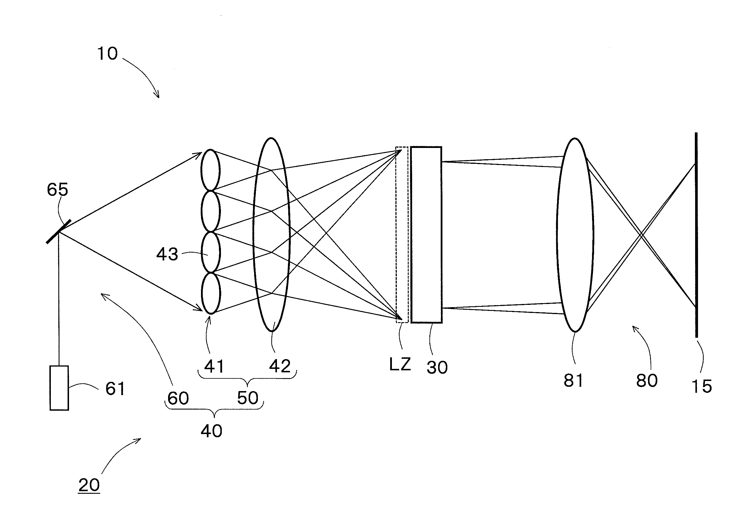
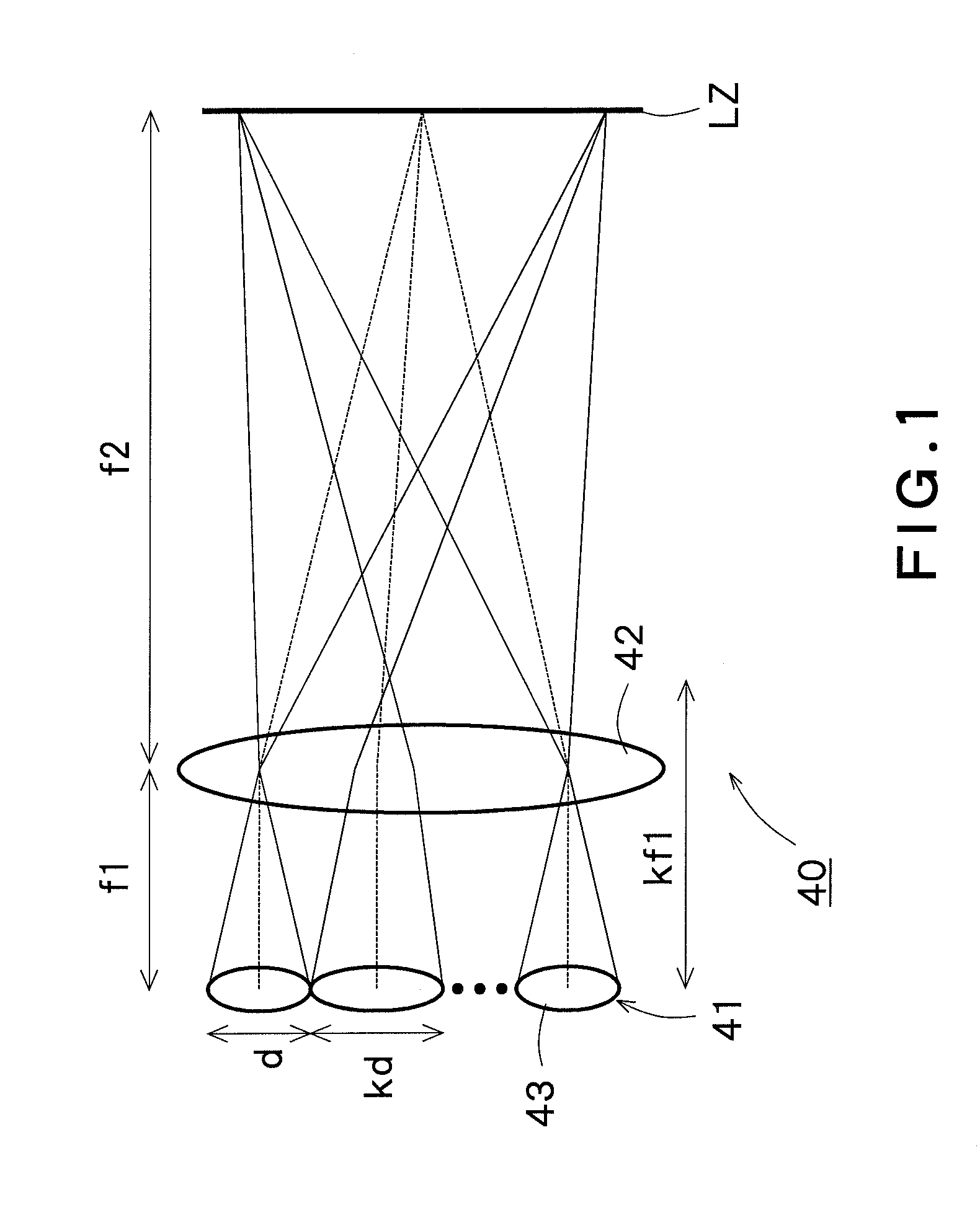
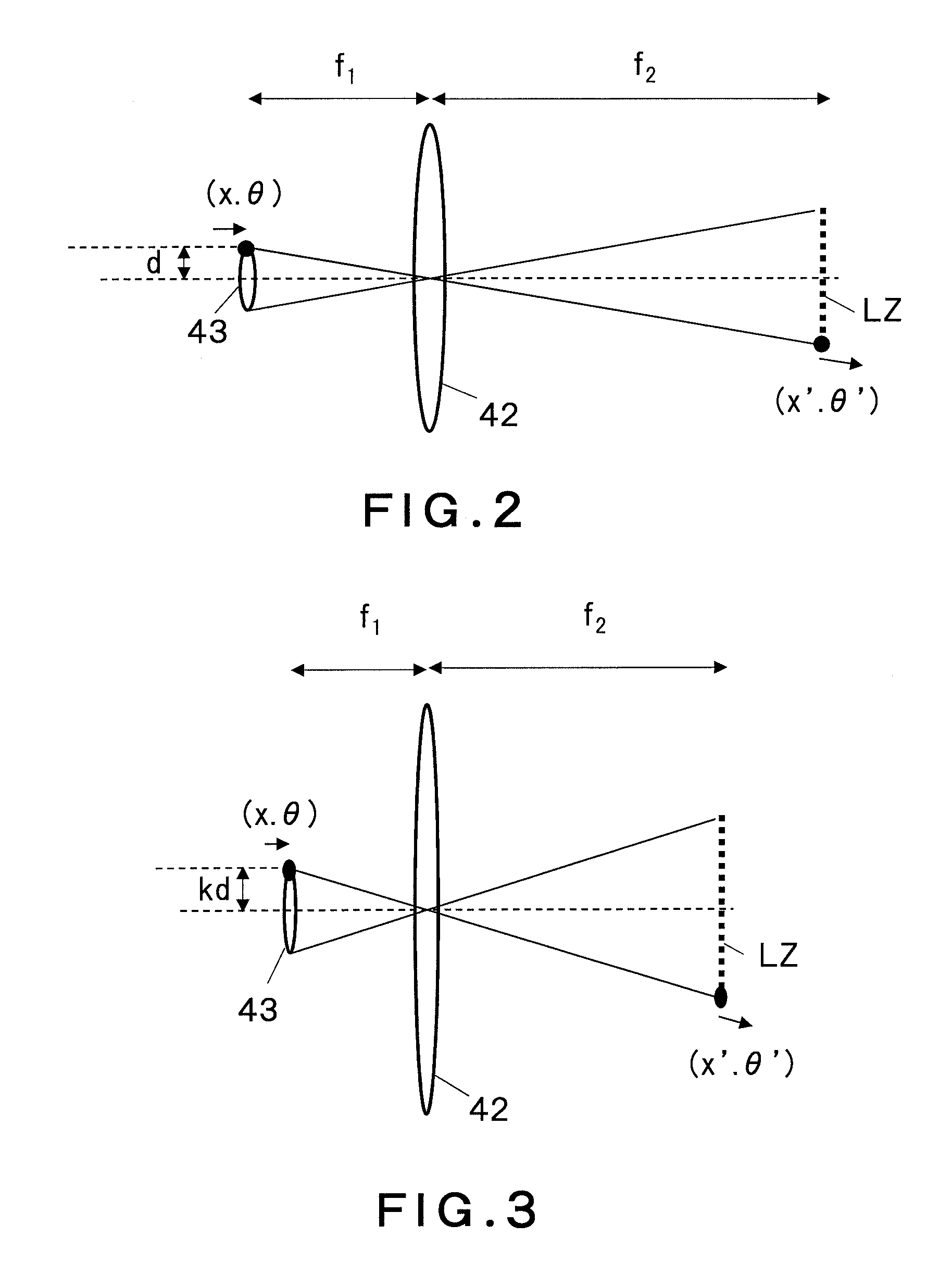
[0036]FIG. 1 is a diagram explaining the essential structure of an illumination device 40 according to a first embodiment of the present invention. The illumination device 40 of FIG. 1 is provided with a lens array 41 and a field lens 42. The lens array (a first lens array) 41 has a plurality of lens elements (first lens elements) 43 arranged vertically and horizontally, namely, in a first direction and in a second direction that intersects with the first direction. The first and second directions are typically two-dimensional directions orthogonal to each other. Each lens element 43 collects coherent light beams incident thereon from a laser source (not shown) and guides the collected coherent light beams to the field lens 42. The field lens 42 guides each of the coherent light beams that have passed through the lens elements 43 to the entire region of a specific zone that is an illumination zone LZ. The specific zone, or the illumination zone LZ is set closer to the focal plane of...
second embodiment
[0087]In a second embodiment which will be explained below, there is another lens array in addition to the lens array 41.
[0088]An illumination device 40 according to the second embodiment is provided with a first lens array 41 that has the shape and optical characteristics identical to those of the lens array 41 of the first embodiment. First lens elements 43 in the first lens array 41 also have the shape and optical characteristics identical to those of the lens elements 43 in the lens array 41 of the first embodiment.
[0089]FIG. 7 is a diagram explaining the essential structure of the illumination device 40 according to the second embodiment of the present invention. The illumination device 40 of FIG. 7 has a second lens array 48 in the optical path between the first lens array 41 and the field lens 42. The second lens array 48 has a plurality of second lens elements 49 associated with the first lens elements 43.
[0090]Each of the second lens elements 49 has the same lens diameter a...
third embodiment
[0099]In the lens array (first lens array) 41 in the above-described first and second embodiments 8, light beams incident on the joints between the lens elements 43 are not used efficiently, hence become useless. It is therefore desirable that there are no joints between the lens elements 43. It is thus effective to use, for example, the cylindrical lens 45 shown in FIG. 4 as the lens array (first lens array) 41. As another realization means, it is also effective to use a toroidal lens such as shown in FIGS. 8 and 9 as the lens array (first lens array) 41. Here, the toroidal lens is a specific lens having a toroidal surface on at least either side of the lens. The toroidal surface is a specific surface that has curvature different in x and y directions, such as the surface of a barrel and a doughnut.
[0100]Toroidal lens arrays 51 and 52 in FIGS. 8 and 9, respectively, have a plurality of toroidal lenses 53 arranged in a first direction X and a second direction Y intersecting with eac...
PUM
 Abstract
Description
Claims
Application Information
 - R&D
- Intellectual Property
- Life Sciences
- Materials
- Tech Scout
- Unparalleled Data Quality
- Higher Quality Content
- 60% Fewer Hallucinations
Browse by: Latest US Patents, China's latest patents, Technical Efficacy Thesaurus, Application Domain, Technology Topic, Popular Technical Reports.
© 2025 PatSnap. All rights reserved.Legal|Privacy policy|Modern Slavery Act Transparency Statement|Sitemap|About US| Contact US: help@patsnap.com