Waterproofing structure, waterproofing method and wireharness

a technology of waterproofing and wireharness, applied in the direction of insulated conductors, cables, cable terminations, etc., can solve the problems of water not being allowed to infiltrate the exterior member, water moving up, and the electrical connection of the shielded connector is adversely affected, so as to achieve no increase in size

Active Publication Date: 2016-06-30
YAZAKI CORP
View PDF6 Cites 26 Cited by
  • Summary
  • Abstract
  • Description
  • Claims
  • Application Information

AI Technical Summary

Benefits of technology

[0012]The present invention provides a waterproofing structure, a waterproofing method, and a wireharness which are capable of reliably performing waterproofing at a predetermined positio

Problems solved by technology

Accordingly, even if water splashing occurs during traveling, water is not allowed to infiltrate into the exterior member.
According to a related art, when water is collected inside of the exterior member for unknown reasons, the collected water may move up to a region in which the shielded connector is provided, that is, an electrical connection portion through a gap between the insulated core wire and the shielding member of the conductive path, which is a problem (also, when the wireharness is submerged underwater due to natural disasters, water may move up to the aforementioned portion).
When a waterproofing structure portion is not provided, electrical connection of the shielded connector is adversely affected.
The disposition of the waterproofing boot as described above leads to an increase in the size of a portion of the wireharness in which the waterproofing boot is disposed, which is a problem.
The size increase leads to a decrease in the degree of freedom in the routing of the wireharness in a vehicle.
In an exam

Method used


Image

  • Waterproofing structure, waterproofing method and wireharness
  • Waterproofing structure, waterproofing method and wireharness
  • Waterproofing structure, waterproofing method and wireharness

Examples


example 1

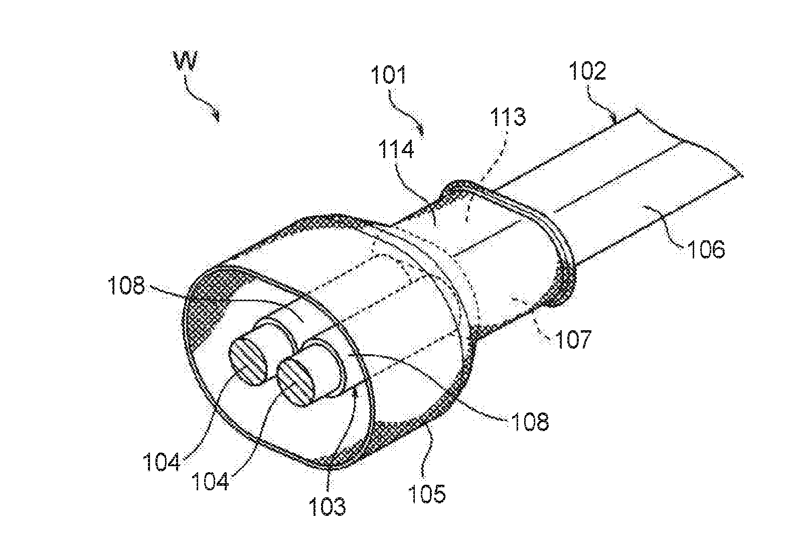
[0034]Hereinafter, Example 1 will be described with reference to the accompanying drawings. FIG. 11 is a perspective view of a waterproofing structure portion which adopts a waterproofing structure of the present invention. FIG. 12 is a perspective view (including a sectional view) of the waterproofing structure portion. FIG. 13 is a sectional view of the waterproofing structure portion. FIG. 14 is a perspective view illustrating a state in which a sheath is cut away to a predetermined length which is up to a target part of waterproofing. FIG. 15 is a perspective view of a waterproofing member. FIG. 16 is a perspective view illustrating a state in which the waterproofing member is assembled to a first folded portion.

101>

[0035]In FIGS. 11 to 13, reference sign 101 represents a waterproofing structure portion provided at a desired position on a wireharness W. The waterproofing structure portion 101 is a portion which adopts a waterproofing structure of the present invention. It can be...

example 2

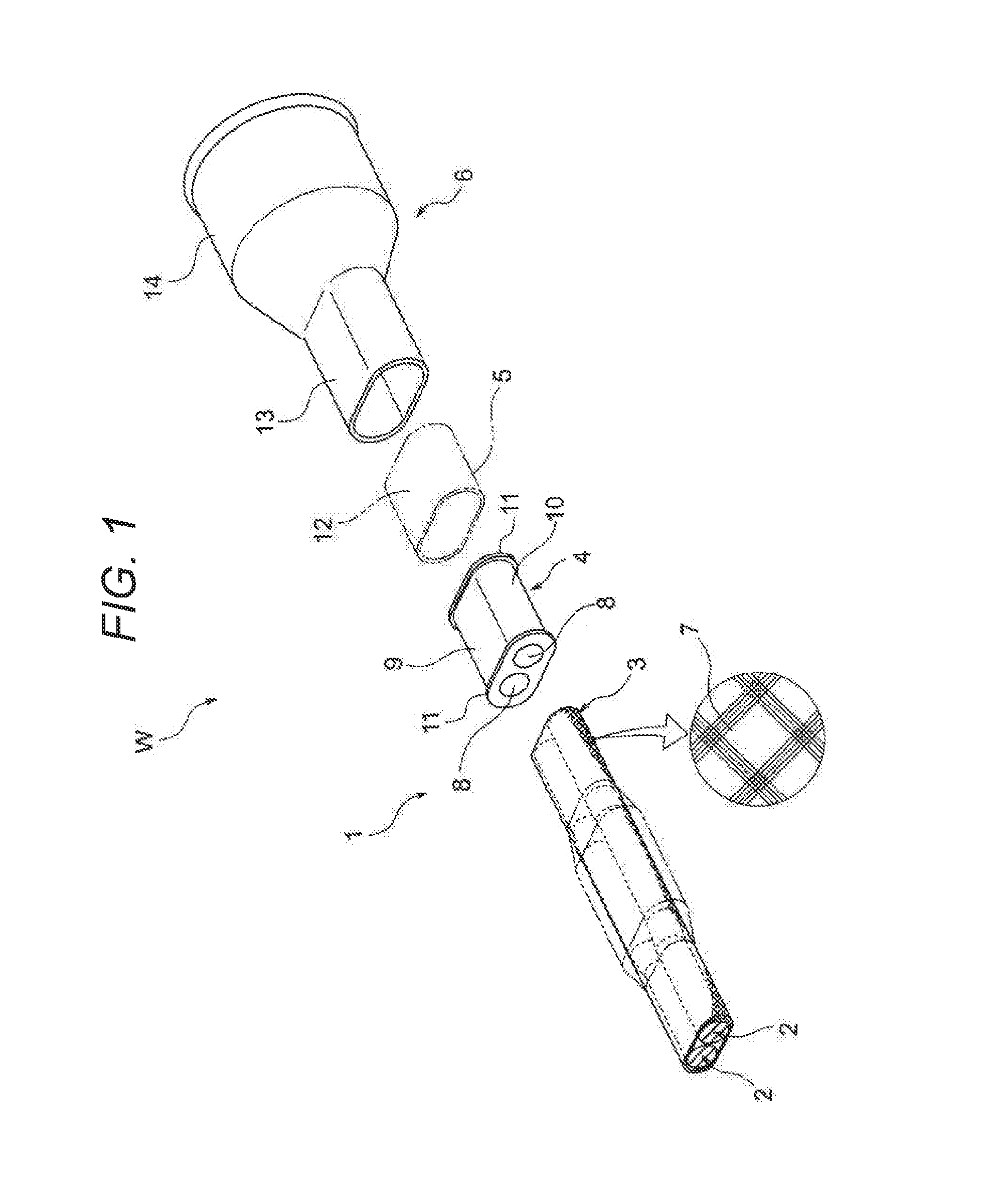
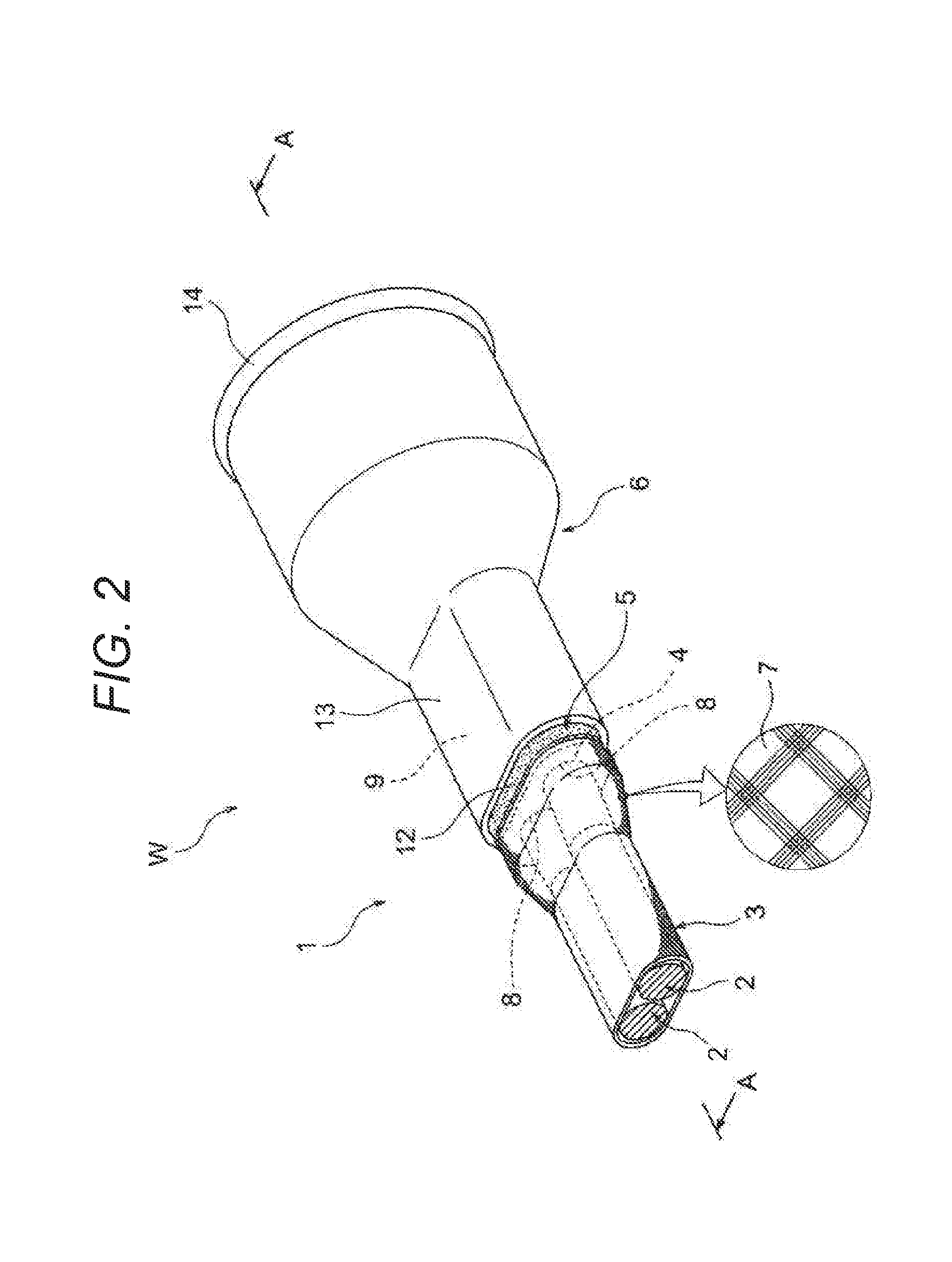
[0063]Hereinafter, Example 2 will be described with reference to the accompanying drawings. FIG. 1 is an exploded perspective view of a waterproofing structure portion which adopts a waterproofing structure of the present invention. FIG. 2 is a perspective view of the waterproofing structure portion in FIG. 1. FIG. 3 is a sectional view of the waterproofing structure portion taken along line A-A in FIG. 2. FIG. 4 is an enlarged view of an essential portion in FIG. 3. FIGS. 5 to 9 are views illustrating each step of a waterproofing method of the present invention.

1>

[0064]In FIGS. 1 to 3, reference sign 1 represents a waterproofing structure portion provided at a desired position on the wireharness W. The waterproofing structure portion 1 is a portion which adopts the waterproofing structure of the present invention. It can be known from the following description that the waterproofing structure portion 1 is a portion structured to be capable of reliably waterproofing a target part of...


PUM


Abstract

Disclosed is a waterproofing structure including: one or multiple insulated core wires; a shielding member configured to collectively cover the one or multiple insulated core wires; a sheath provided on the outside of the shielding member; and a waterproofing member provided at a target part of waterproofing. The target part of waterproofing is positioned where a sheath end portion is formed by cutting away the sheath to a predetermined length, and the shielding member is exposed from the sheath end portion. The waterproofing member is shaped to include a bottomed cylindrical body including a bottom portion, and one or multiple tubular portions which open up the bottom portion and continue with an outer surface of the bottom portion.

Description

CROSS-REFERENCES TO RELATED APPLICATIONS[0001]This application is based on and claims priority from Japanese Patent Application Nos. 2014-259681 filed on Dec. 24, 2014 and 2014-259682 filed on Dec. 24, 2014, the entire contents of which are incorporated herein by reference.BACKGROUND[0002]1. Field of the Invention[0003]The present invention relates to a waterproofing structure that includes one or multiple insulated core wires, a shielding member collectively covering the one or multiple insulated core wires, a sheath provided on the outside of the shielding member, and a waterproofing member provided on a target part of waterproofing, and to a waterproofing method. In addition, the present invention relates to a wireharness which adopts the waterproofing structure of a waterproofing structure portion.[0004]2. Description of Related Art[0005]As an example of a high-voltage wireharness, Patent Document 1 discloses a wireharness through which high-voltage devices mounted in a hybrid v...

Claims


Application Information

Patent Timeline
IPC IPC(8): H01B7/282B60R16/02H01B13/012H01B7/00
CPCH01B7/282H01B13/012B60R16/0215H01B7/0045H02G15/013H02G15/04
Inventor OGA, TATSUYAKUBOSHIMA, HIDEHIKOADACHI, HIDEOMI
Owner YAZAKI CORP
Why Eureka
Try Eureka