

Bioreactor with addition tube
a technology of addition tubes and bioreactors, which is applied in the field of bioreactors, can solve the problems of poor control of reagent supply, cell death and release of detrimental signal substances, and preventing proper distribution in the cultur
- Summary
- Abstract
- Description
- Claims
- Application Information
AI Technical Summary
Benefits of technology
Problems solved by technology
Method used
Image

Examples
Embodiment Construction
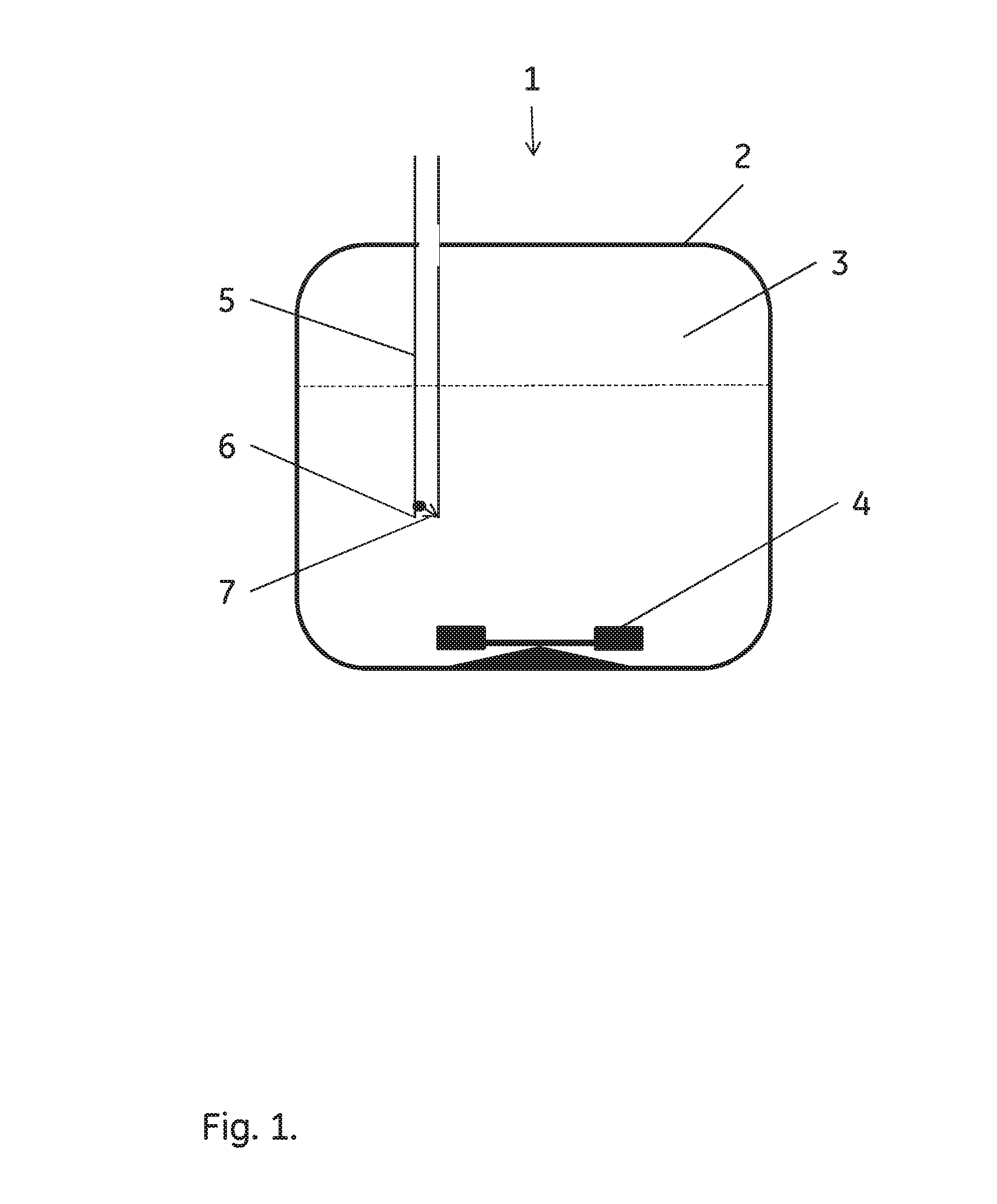
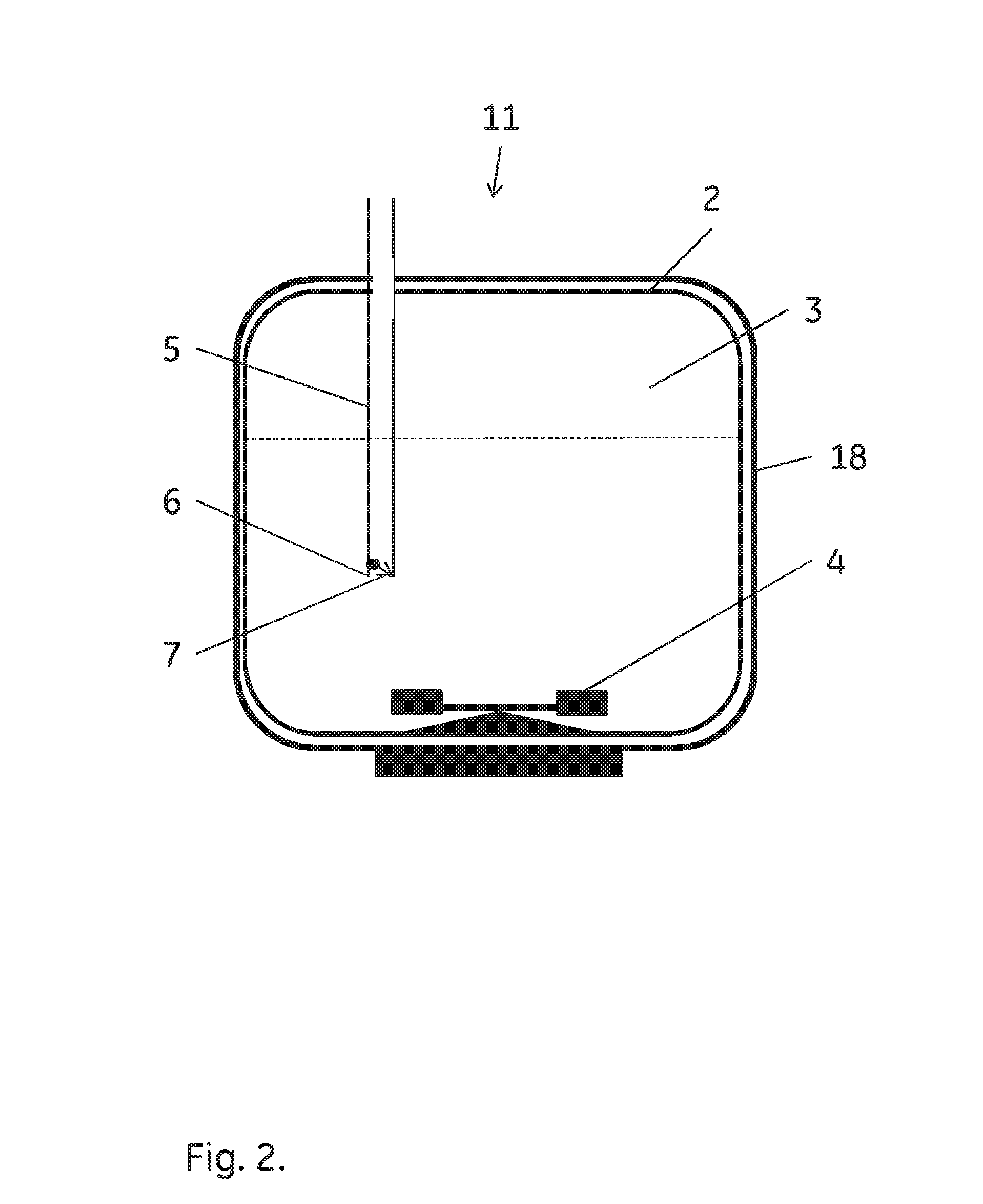
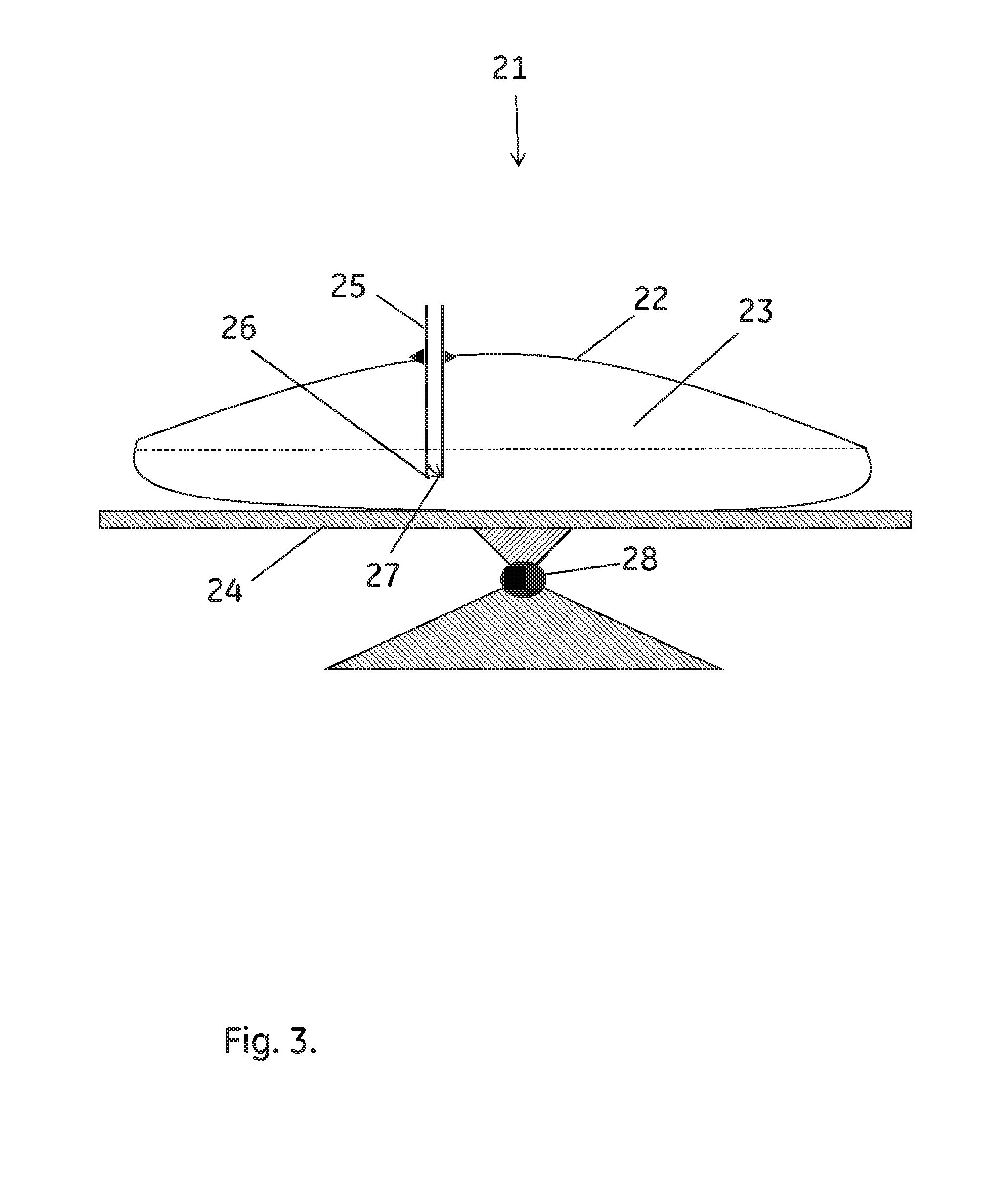
[0015]In one aspect the present invention discloses a bioreactor 1;11;21 comprising a vessel 2;22 which defines an inner volume 3;23. The bioreactor further comprises agitation means 4;24 and at least one addition tube 5;25, where a delivery orifice 6;26 in the addition tube is located within the inner volume of the vessel and a check valve 7;27 is arranged in proximity of, or adjacent, the delivery orifice such that it allows flow of a fluid in the direction from the addition tube into the inner volume 3;23 and blocking flow in the reverse direction. When check valve 7;27 is arranged in proximity of delivery orifice 6;26, the distance between the check valve and the orifice may be e.g. up to 20 times the diameter of tube 5;25, such as up to 10 times, up to 5 times or up to 2 times the diameter of tube 5;25 (or the average diameter if the diameter varies along the length of tube 5;25). Short distances are advantageous due to the smaller dead volumes, but it can be easier to accommod...
PUM
| Property | Measurement | Unit |
|---|---|---|
| opening pressure | aaaaa | aaaaa |
| opening pressure | aaaaa | aaaaa |
| opening pressure | aaaaa | aaaaa |
Abstract
Description
Claims
Application Information