
Frameless construction using single and double panels

a frameless, single-panel technology, applied in the direction of walls, building roofs, building repairs, etc., can solve the problems of affecting the stability of the structure, the inability to meet the needs of modular housing, so as to eliminate eliminate the need for thermal breaks, and the effect of reducing the need for ductwork

Inactive Publication Date: 2016-07-07
WALKER JAMES
View PDF65 Cites 10 Cited by
  • Summary
  • Abstract
  • Description
  • Claims
  • Application Information

AI Technical Summary

Benefits of technology

The patent describes a new construction method using frameless single and multi-plenum panels. This method has advantages such as easy transportation and assembly in the field in one day, which saves time, labor, and materials. The panels have weatherproof sheathing and can be closed to the weather in one day. The single plenum panels with two sheets and an interior matrix stabilize the load-bearing sheet from buckling. The method also eliminates thermal breaks and provides full thermal envelope with full exterior ventilation. The panels provide air distribution and eliminate the need for ductwork. The patent notes that the disclosed construction method is suitable for code compliance and health and energy efficiency in the walls and roofs.

Problems solved by technology

All of this framing incurs costs of time, labor, materials, and extended exposure of the interior building materials to the elements while the building remains uncovered.
And although traditional modular construction results in an expedited house once the modular pieces are at the construction site, modular homes still use stick framing at the factory and still has the associated time, labor, materials and cost as stick built or conventionally framed buildings.
Additionally, modular homes incur extra costs and special requirements for transporting the modular pieces to the construction site.
Similarly, manufactured housing, whether single wide, double wide or triple wide, is also constructed using traditional use stick framing at the factory and still has the associated time, labor, materials and cost as stick built or conventionally framed buildings.
Additionally, manufactured homes incur extra costs and special requirements for transporting the modular pieces to the construction site.
The framing members cause a thermal short in the thermal envelope and also allows for incomplete insulation installation because of framing members and the many of corners, blocking, headers, as well as the many hap-hazard holes drilled for the installation of plumbing, mechanical and electrical systems.
The result with conventional framing is an insulating layer that is incomplete with leaks and thermal breaks at the studs; all reducing thermal performance.

Method used


Image

  • Frameless construction using single and double panels
  • Frameless construction using single and double panels
  • Frameless construction using single and double panels

Examples


second embodiment

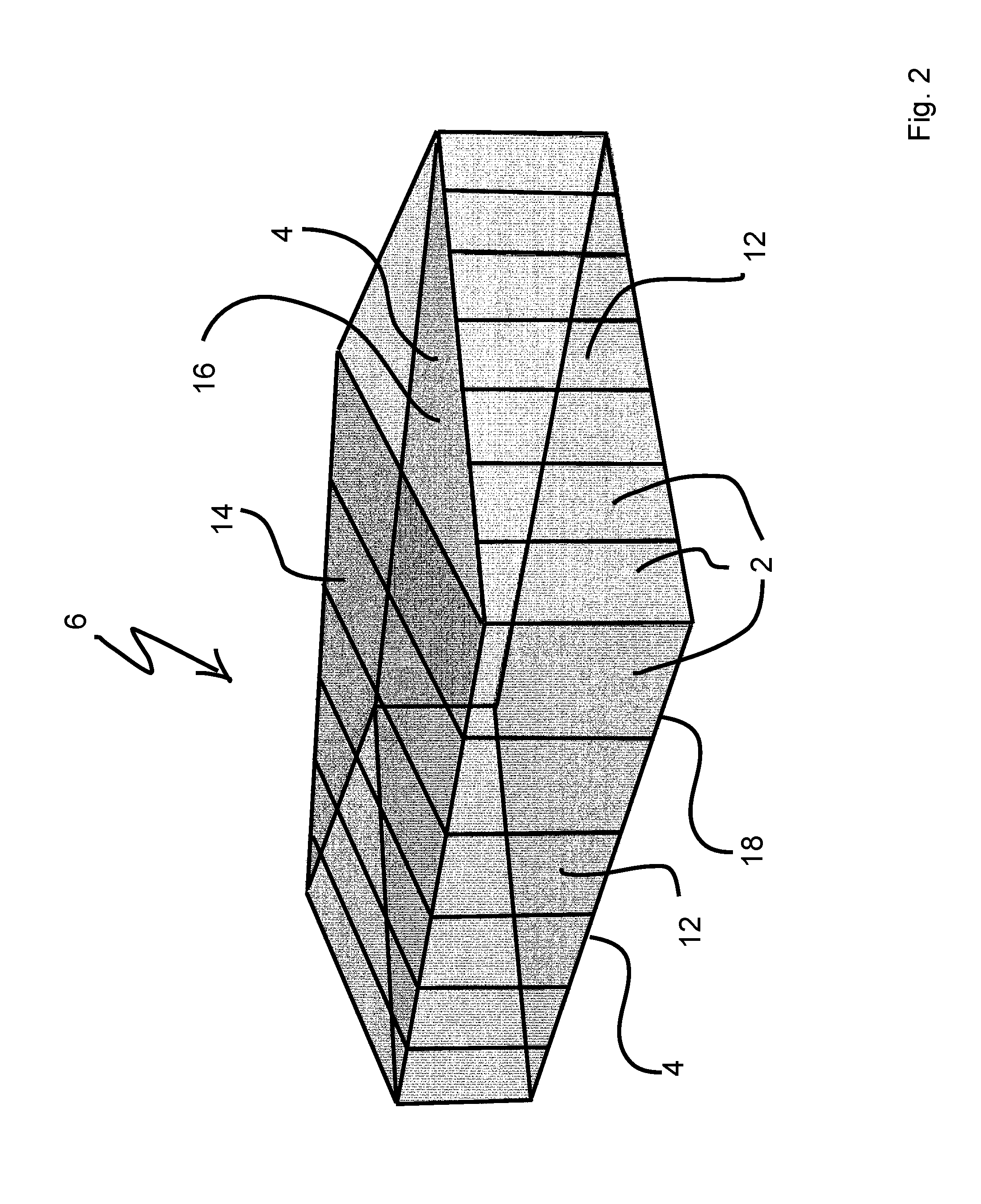
[0092]Turning next to FIG. 2, a second embodiment is shown. In this embodiment, the house 6 is also built without a frame, but instead of continuous panels 8, 10, its walls 12, floor 18, ceiling 16, and roof 14 are built of smaller single and multi-plenum panels 2, 4—typically sized 8 feet by 4 feet, and herein referred to as unit panels 2, 4. These unit panels 2,4 are each easier to handle and individually are faster to erect. But, because of the many number of unit panels necessary, the total installation time can be longer than the house in FIG. 1 utilizing continuous panels.

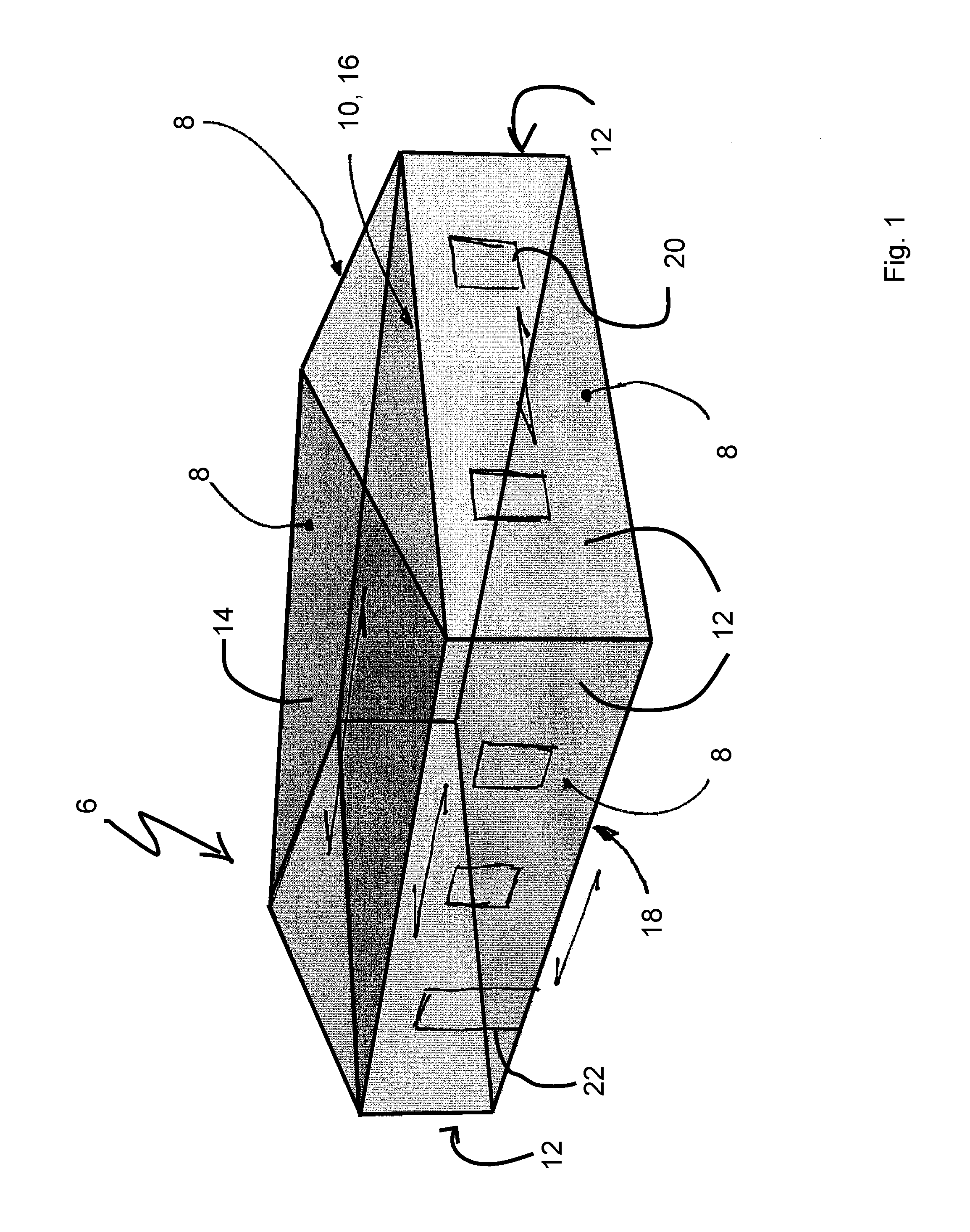
[0093]It should also be noted that an embodiment (not shown) utilizing a combination of both unit 2, 4 and continuous 8, 10 panels in a single building 6 construction falls within the scope of this invention. As just one example, the building may have walls 12 with unit panels 2, 4 as shown in FIG. 2, and floors 18, ceiling 16, and roof 14 with continuous panels 8, 10 as shown in FIG. 1.

[0094]Turning next to ...

first embodiment

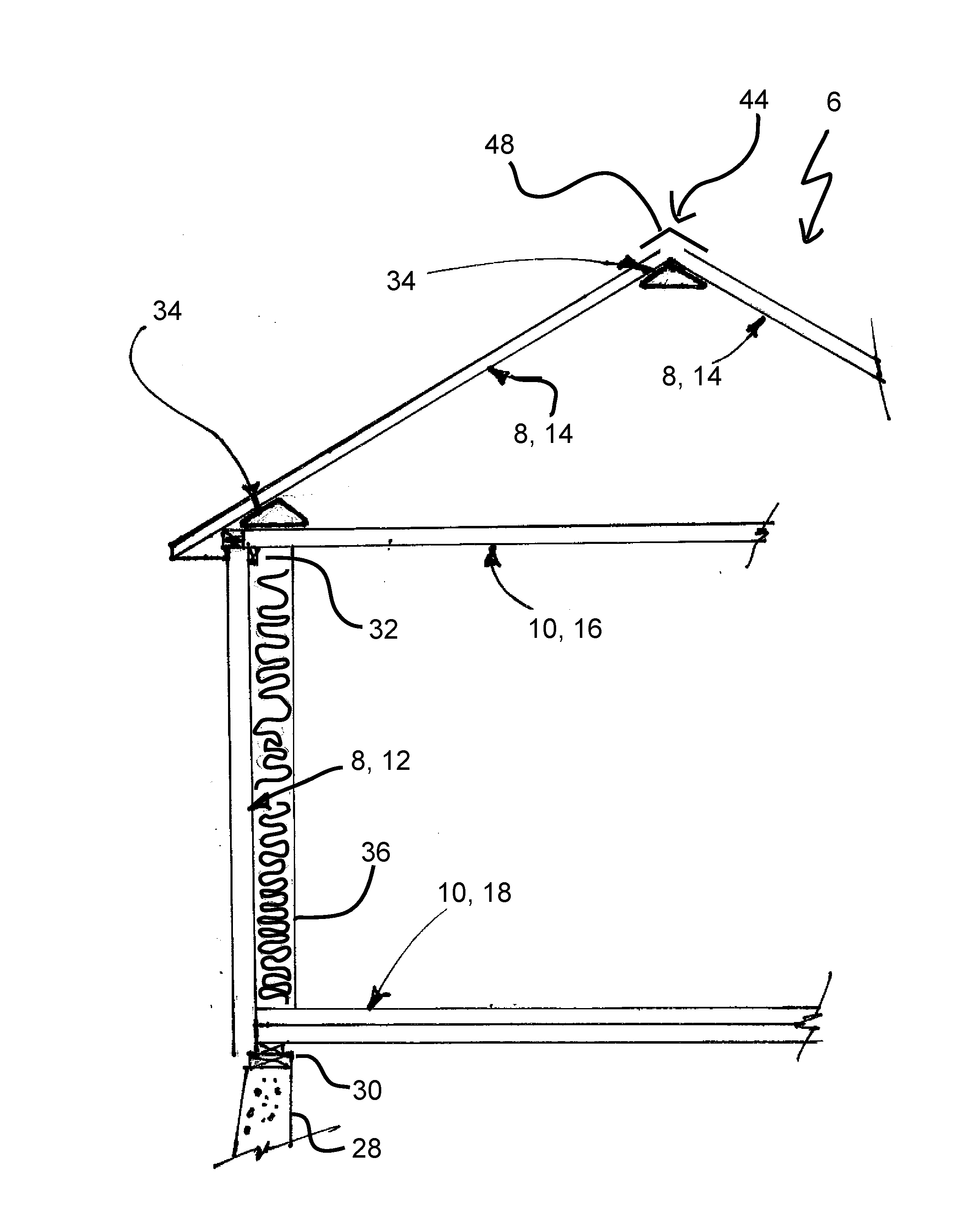
[0103]Turning now to FIG. 4, the roof connector 34 is shown. The roof connector 34 is anticipated to be continuous hollow triangular prism, most likely formed of the same material along each side. The roof connectors are designed to resist downward and upward forces as well as lateral or horizontal sheer forces and bending forces or moments. The roof connectors 34, via mechanical and / or adhesive connections to adjacent single and / or multi plenum panels, are designed to be an integral part of the structural system increasing the structural strength of the building.

[0104]This is a typical roof connector 34 made of wood. It is anticipated that it would be constructed of long strips of plywood or OSB with staggered joints, and / or finger-jointed material. The roof connector 34 could also be constructed from typical “2×” lumber of 1½″ thickness.

[0105]The roof connector 34 will typically have at least one roof adjacent surface 38 that attaches to the roof panel 14. For roof connectors 34 u...

third embodiment

[0155]In this third embodiment, a lower single plenum panel 2, 8 wall panel 12 is assembled using methods previously described as a load bearing wall 12. Lower wall blocking 32 is preferably mechanically and adhesively attached to top of the interior sheet 54 sheet of the lower single plenum panel 2, 8 wall 12 to support a horizontal multi plenum panel 4, 10, which is used for both the lower level ceiling 16 and the upper level floor 18. This horizontal multi-plenum panel 4, 10 has edge blocking 70 to facilitate mechanical and adhesive attachment to the lower wall blocking 32.

[0156]After installation of the horizontal multi-plenum panel 4, 10, an upper (vertically oriented) load bearing single plenum panel 2, 8 wall panel 12 is placed on and vertically aligned with the lower wall panel 12, as shown in FIG. 17. The upper wall panel 12 is preferably mechanically and adhesively attached to the edge blocking 70 and an additional upper wall blocking 32 added to the second floor level. Th...


PUM


Abstract

A method of constructing a budding comprising the steps of attaching a first panel to a second panel. The first panel is one of a single plenum panel and a multi-plenum panel and the second panel is one of a single plenum panel and a multi-plenum panel.

Description

CROSS REFERENCE TO RELATED APPLICATIONS[0001]This application claims priority to United States Provisional Patent Application Nos. 62 / 210,616 filed Aug. 28, 2015, the contents of which are incorporated herein by reference in its entirety, and 62 / 100,660 filed Jan. 7, 2015, the contents of which are incorporated herein by reference in its entirety.FIELD OF THE INVENTION[0002]This invention relates to methods and devices for frameless building construction utilizing single and multi-plenum panels with various spacing structural elements.BACKGROUND OF THE INVENTION[0003]Conventional wood homes and structures are built in stages, with wood framing erected first, and sheathing attached at a later date. Usually, homes and other wooden structures are built using “2 by” framing, normally from the ground up. For example, 2×10's are normally used for joists for floors, typically 16 inches on center, and are covered with sheathing for a floor deck, typically in 4′×8′ sheets of OSB or plywood.[...

Claims


Application Information

Patent Timeline
IPC IPC(8): E04B1/41E04B5/02E04B9/04E04B2/72E04B7/20
CPCE04B1/40E04B2/72E04B5/023E04B9/04E04B7/205E04B1/10E04B1/61E04B1/7612E04B1/388
Inventor WALKER, JAMES
Owner WALKER JAMES
Learn More