Device for transforming an out-of-plane movement into an in-plane movement, and/or vice-versa

a technology of in-plane movement and out-of-plane movement, applied in the direction of mechanical control devices, process and machine control, instruments, etc., can solve the problem of only having limited energy to carry out actuation on a given device surface area

Active Publication Date: 2016-07-07
COMMISSARIAT A LENERGIE ATOMIQUE ET AUX ENERGIES ALTERNATIVES
View PDF0 Cites 7 Cited by
  • Summary
  • Abstract
  • Description
  • Claims
  • Application Information

AI Technical Summary

Benefits of technology

[0021]The system of the invention allows the rotationally mobile element to be rotated about a neutral position.

Problems solved by technology

This type of actuator has the advantage of providing in-plane actuation but the disadvantage of only having limited energy to carry out actuation on a given device surface area.

Method used


Image

  • Device for transforming an out-of-plane movement into an in-plane movement, and/or vice-versa
  • Device for transforming an out-of-plane movement into an in-plane movement, and/or vice-versa
  • Device for transforming an out-of-plane movement into an in-plane movement, and/or vice-versa

Examples


Embodiment Construction

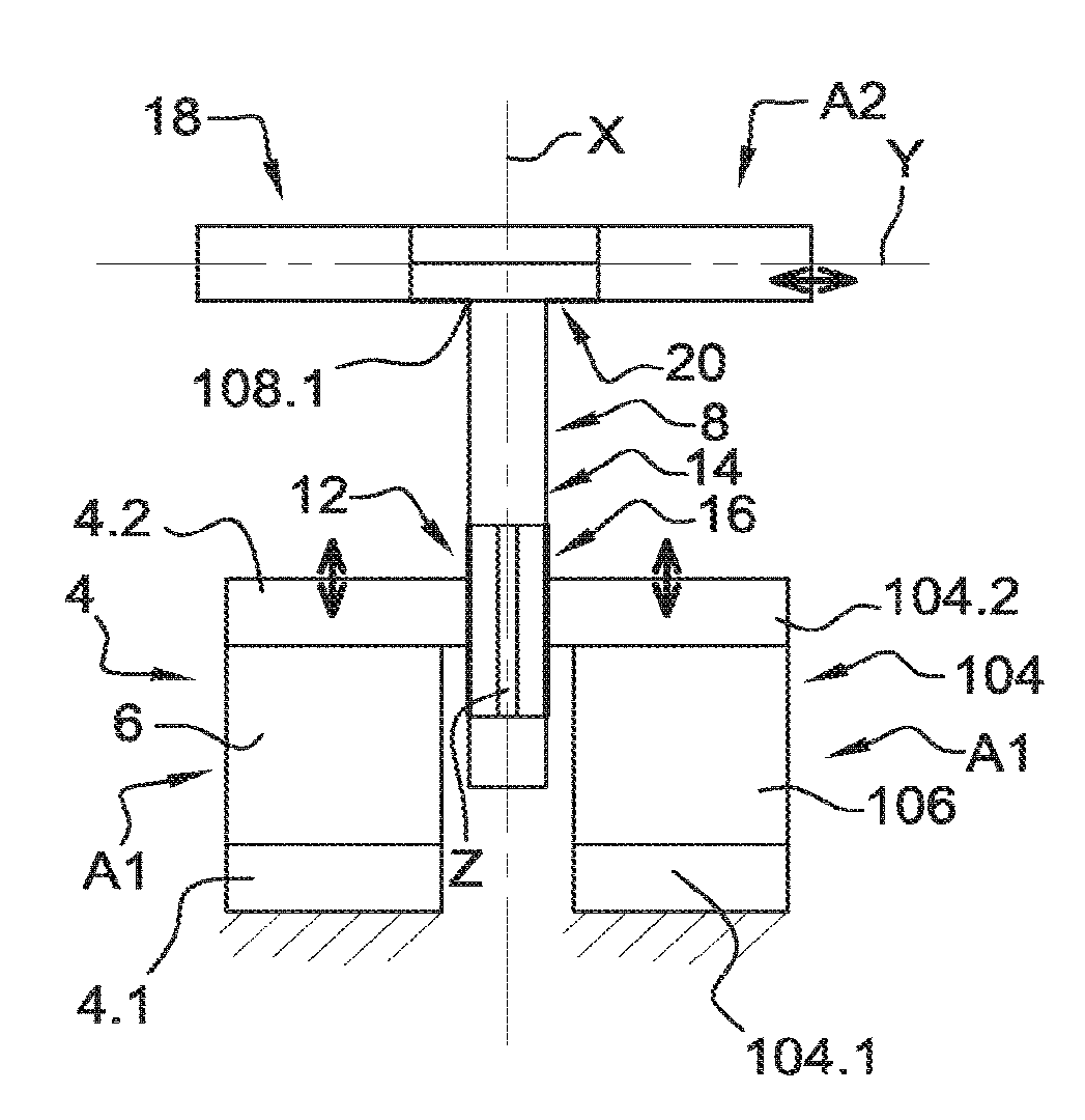
[0049]In the following description the device to convert out-of-plane motion to in-plane motion and / or conversely is described with application to an actuator. However, the present invention is not limited to application to an actuator but extends to any device able to implement said motion conversion.

[0050]In the present application by “deformable element” is meant an element having an initial configuration and which can be elastically deformed by application of a stimulus e.g. under strain resulting from heating or the application of an electric or magnetic field or application of an acceleration. The deformable element resumes its initial configuration when no longer constrained.

[0051]Also, when reference is made to the plane, the plane is the median plane of the device parallel to the plane of the substrate.

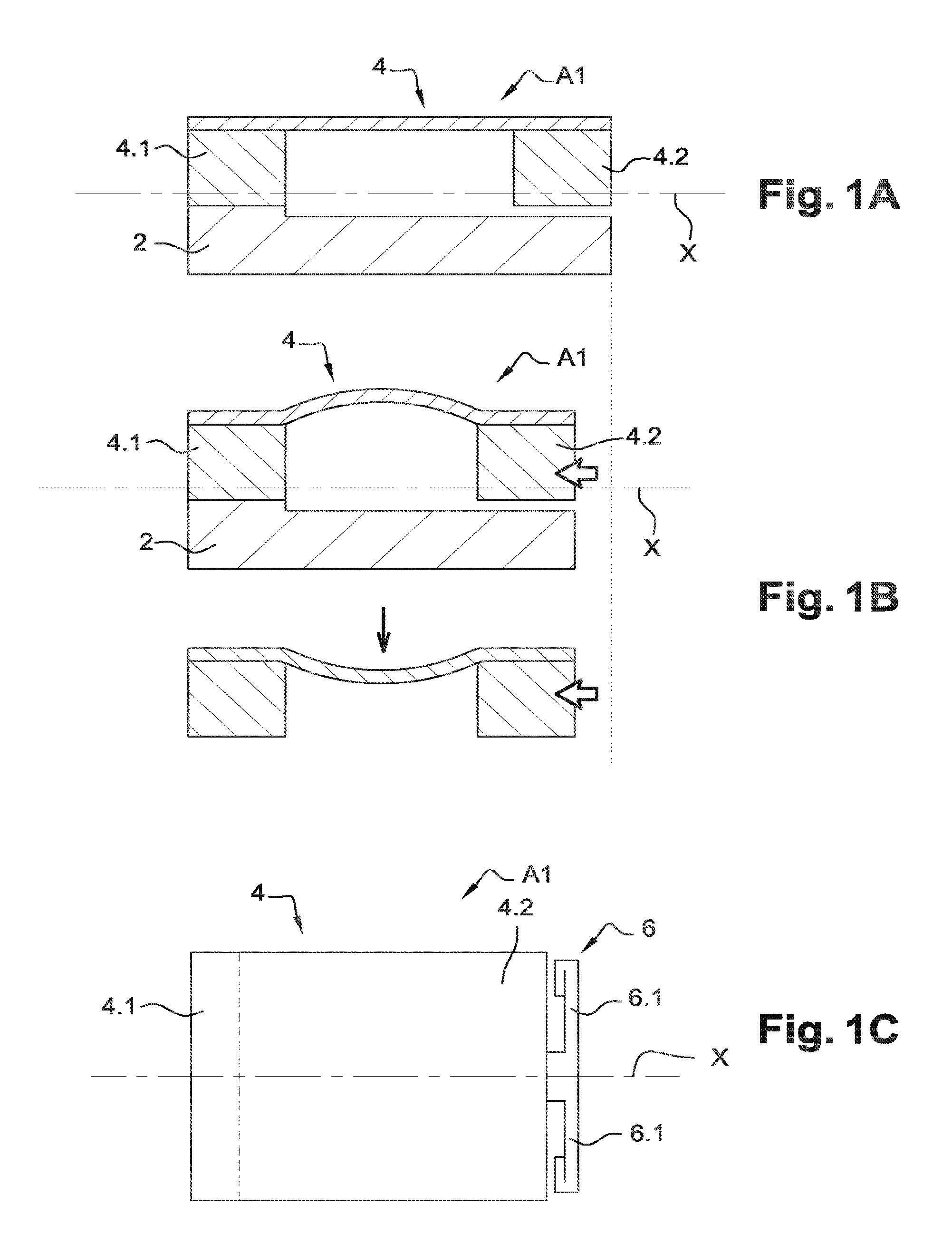
[0052]FIGS. 1A to 1C show an example of an actuator A1 of the invention comprising a substrate 2 and a deformable element 4 extending in a direction X contained in the plane ...


PUM


Abstract

An actuator comprising two devices each comprising an out-of-plane deformable element, said deformable element comprising a first fixed end anchored on a substrate and a second free end relative to the substrate, said device also comprising means to guide the second free end in in-plane translation along a first direction, the first deformable element being capable of deforming out-of-plane through application of a stimulus so that the second free end draws close to the first fixed end following in-plane translational movement. The actuator also comprises an element mobile in rotation about an axis orthogonal to the plane and mechanically linked to the free ends of the deformable elements, and a translationally mobile element mechanically linked to the rotationally mobile element.

Description

TECHNICAL FIELD AND STATE OF THE PRIOR ART[0001]The present invention relates to a device to convert out-of-plane motion to in-plane motion and / or to convert in-plane motion to out-of-plane motion, in particular in microsystems or nanosystems, and to an actuator comprising said device.[0002]In MicroElectroMechanical Systems (MEMS) and / or NanoElectroMechanical Systems (NEMS) it is sought to produce microactuators and / or nanoactuators to set objects in motion, for example to obtain microswitches. It is more particularly sought to produce actuators in the plane of the MEMS and / or NEMS.[0003]Actuators of electrostatic type exist comprising a fixed comb and mobile comb having interdigitated fingers and between which a voltage difference is applied causing the onset of electrostatic forces which tend to draw the fingers together and thereby set the mobile comb in motion. This type of actuator has the advantage of providing in-plane actuation but the disadvantage of only having limited ene...

Claims


Application Information

Patent Timeline
Patent Type & Authority Applications(United States)
IPC IPC(8): G05G11/00H01L41/08
CPCH01L41/08G05G11/00B81B3/0051H01H1/0036B81B2201/032B81B2201/037B81B2203/051H01H2001/0078H10N30/00
Inventor HILT, THIERRY
Owner COMMISSARIAT A LENERGIE ATOMIQUE ET AUX ENERGIES ALTERNATIVES
Why Eureka
Try Eureka