Method and device for compensation of temporal magnetic field fluctuations in powered magnets

a technology of powered magnets and magnetic field fluctuations, applied in the direction of superconducting magnets/coils, permanent magnets, electric circuit arrangements, etc., can solve the problems of inability to achieve high resolution nmr spectroscopy and mr imaging, inability to adjust the frequency of ffls, and inability to achieve high resolution nmr imaging, etc., to achieve the effect of lower fluctuations of powered magnets and reducing the frequency of higher frequency fluctuations

Active Publication Date: 2016-07-07
PENN STATE RES FOUND
View PDF1 Cites 2 Cited by
  • Summary
  • Abstract
  • Description
  • Claims
  • Application Information

AI Technical Summary

Benefits of technology

[0013]The MR signal spectra is characterized by its centroid, or Larmor frequency, which is always directly proportional to the strength of the static magnetic field, and linewidth, which is typically characterized by the full-width half-maximum metric. The Higher frequency field fluctuations due to power supply ripple at harmonics of 60 Hz distort the lineshape of NMR spectra, and lower frequency field fluctuations due to variations in cooling water temperature and flow rate shift the frequency of consecutive MR spectra peaks. Earlier studies have shown that inductive feedback control significantly reduces higher frequency fluctuations in powered magnets. Additionally, NMR feedback control, or field-frequency locks (FFLs), reduces lower frequency fluctuations in persistent mode magnets. These FFLs are in general not designed for powered magnets where higher frequency fluctuations are present.
[0016]After a MR signal is acquired, the indirect FFL control system switches to a lock mode in the presence of field fluctuations that change rapidly with respect to a dominant time constant of MR signal dynamics governing a lock signal, without the necessity of switching to the sweep mode and a proportional-plus-integral-plus derivative algorithm adjusts the field generated by the correction coil to regulate the magnitude of the dispersion component to zero. By maintaining the dispersion component at zero, the feedback system cancels field fluctuations that would otherwise change the phase, and hence Larmor frequency of the MR response.
[0019]The present disclosure integrates a FFL design with a previous inductive feedback control design to reduce lower and higher frequency fluctuations in powered magnets. Digital sampled-data compensators are designed for the inductive feedback control loop in series with a FFL control loop, forming a cascade feedback control system. This approach was evaluated experimentally using NMR spectra peak frequencies and lineshape derived from free-induction decay (FID) measurements in the Keck powered magnet operating at 25 T.
[0020]The present disclosure uses a combination of an inductive feedback control with a direct FFL to reduce higher and lower frequency fluctuations in powered magnets. The inductive feedback control loop was placed in cascade with the direct FFL control loop, forming a cascade feedback control system. Three methods for direct estimation where investigated as a sensor for the direct FFL, and a corresponding compensator design for this FFL control loop was developed. The cascade feedback control system improved FID spectra peak frequency and absorption line-shape for measurements obtained using the Keck powered magnet.
[0022]Implementing the cascade feedback control system in the presence of field gradients improves certain NMR experiments such as gradient enhanced spectroscopy and two dimensional NMR. Additionally, the system can be used for magnetic resonance imaging (MRI) that requires field gradients by reducing field fluctuations in the presence of such field gradients.

Problems solved by technology

Powered magnets provide substantially higher magnetic fields than persistent mode magnets, but their spatial field inhomogeneities and temporal field fluctuations are unacceptable for high resolution NMR spectroscopy and MR imaging.
These FFLs are in general not designed for powered magnets where higher frequency fluctuations are present.
As a result, the sweep process may require several minutes, during which NMR spectroscopy experiments cannot be performed.

Method used


Image

  • Method and device for compensation of temporal magnetic field fluctuations in powered magnets
  • Method and device for compensation of temporal magnetic field fluctuations in powered magnets
  • Method and device for compensation of temporal magnetic field fluctuations in powered magnets

Examples


Embodiment Construction

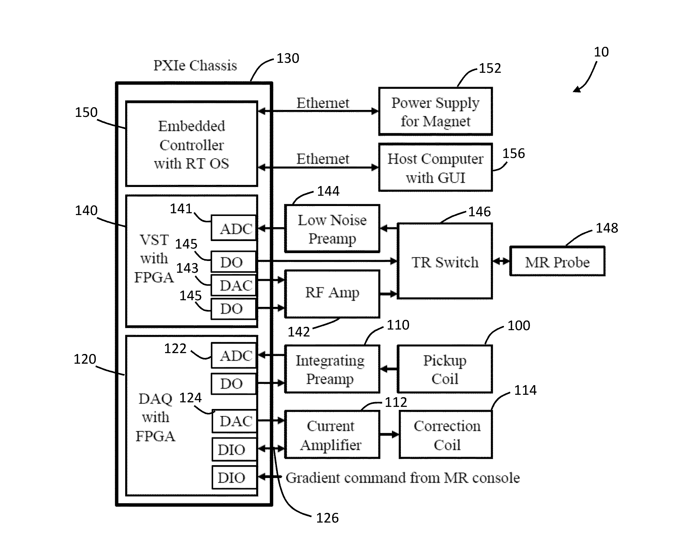
[0039]A system and method for compensating or reducing temporal magnetic field fluctuations in powered magnets is provided. The system includes a magnetic coil that generates a high magnetic field and a fluctuating magnetic field, and a power supply with an AC / DC converter that delivers electric current to the magnetic coil. A cascade control circuit is also included. The cascade control circuit has an inner control loop that outputs an inner loop signal and an outer control loop that outputs an outer loop signal. Also, the inner control loop has a pickup coil and an analog integrating preamplifier, and the outer control loop has a MR field estimator that estimates the Larmor frequency of the MR response.

[0040]The inner control loop senses fluctuations of the fluctuating magnetic field over 1 Hz and the outer control loop senses fluctuations in the magnetic field from direct current (DC) to 20 Hz. In addition, the cascade control circuit generates a correcting magnetic field that ca...


PUM

PropertyMeasurementUnit
frequencyaaaaaaaaaa
frequencyaaaaaaaaaa
frequencyaaaaaaaaaa

Abstract

A system for reducing temporal fluctuations in a powered magnet. The system includes a magnetic field generator that generates a magnetic field with temporal fluctuations and a power supply having an AC / DC converter that delivers electric current to the magnetic field generator. A cascade compensator having an inner control loop that outputs an inner loop signal and an outer control loop that outputs an outer loop signal is included. The inner control loop has a pickup coil and an analog integrating preamplifier and the outer control loop has a magnetic resonance field estimator. The inner control loop senses fluctuations of the magnetic field over 1 Hz and the outer control loop senses fluctuations of the magnetic field from DC to 20 Hz. The cascade compensator generates a correcting magnetic field that cancels the fluctuations based on the inner loop signal and the outer loop signal.

Description

RELATED APPLICATION[0001]This application claims priority of U.S. Provisional Patent Application Ser. No. 62 / 099,791 filed Jan. 5, 2015, which is incorporated in its entirety herein by reference.GOVERNMENT SPONSORSHIP[0002]The invention was made with government support under Contract Nos. DMR0603042 and DMR1039938, awarded by The National Science Foundation. The Government has certain rights in the invention.RELATED FIELD[0003]The present disclosure is related to compensation of temporal magnetic field fluctuations and particularly to compensation of temporal magnetic field fluctuations in powered magnetics using a cascade compensator.BACKGROUND[0004]Nuclear magnetic resonance (NMR) resonance spectroscopy and magnetic resonance (MR) imaging require an external static magnetic field to polarize the magnet moment of nuclei. The quality of the static magnetic field is gauged by its strength, spatial homogeneity, and temporal stability. Low-temperature superconductors (LTS) operating in...

Claims


Application Information

Patent Timeline
Patent Type & Authority Applications(United States)
IPC IPC(8): H01F7/06H01F6/00H01F7/02
CPCH01F7/064H01F6/008H01F7/0278
Inventor SCHIANO, JEFFREY L.THOMSON, BRIAN F.
Owner PENN STATE RES FOUND
Why Eureka
Try Eureka