Attenuation circuit for an energy storage device and method for attenuating oscillations of the output current of an energy storage device

A technology of output current and attenuation circuit, which is applied in the conversion device of irreversible DC power input to AC power output, output power conversion device, and DC circuit can reduce harmonics/ripples, etc., and can solve problems such as unwanted resonance. Achieve the effect of reducing structural space requirements, reducing costs and improving efficiency

Active Publication Date: 2015-04-01
ROBERT BOSCH GMBH
View PDF7 Cites 3 Cited by
  • Summary
  • Abstract
  • Description
  • Claims
  • Application Information

AI Technical Summary

Problems solved by technology

This means that undesired resonances can occur when coupling an energy storage device to a load acting as a variable power source, such as an inverter and a motor connected downstream of the inverter

Method used


Image

  • Attenuation circuit for an energy storage device and method for attenuating oscillations of the output current of an energy storage device
  • Attenuation circuit for an energy storage device and method for attenuating oscillations of the output current of an energy storage device
  • Attenuation circuit for an energy storage device and method for attenuating oscillations of the output current of an energy storage device

Examples


Embodiment Construction

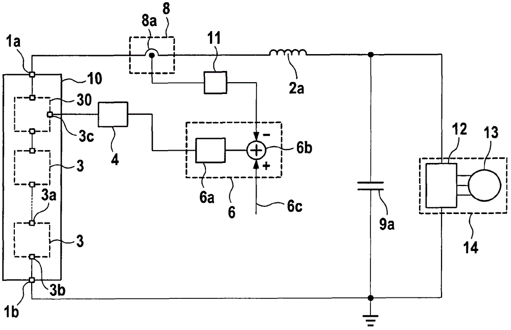
[0027] figure 1 Shown is a system comprising an energy storage device 10 for passing through energy storage modules 3 connected in series in an energy supply line between two output terminals 1a, 1b of the energy storage device 10 supply voltage. Alternatively, the energy storage device 10 can also have a plurality of energy supply lines connected in parallel. The energy storage device 10 acts as a power source with variable output current according to the control of the energy storage module 3 .

[0028]The energy storage device 10 can in this case be coupled to the input connection of the direct voltage intermediate circuit 9 a via the energy storage inductance 2 a at the output connection 1 a of the energy storage device 10 . The energy storage inductance 2a can be realized, for example, by a lumped element, such as a current-limiting coil, or by a plurality of distributed elements. Alternatively, the parasitic inductance of energy storage device 10 can also be used as e...


PUM


Abstract

The invention relates to an attenuation circuit for an energy storage device having one or more energy storage modules which are connected in series in one or more energy supply lines and have at least one energy storage cell and a coupling device which has a multiplicity of coupling elements and is designed to selectively switch or bridge the energy storage cell in the respective energy supply line. The attenuation circuit comprises a current detection device which is designed to detect an output current of the energy supply lines or of the energy storage device and to generate an output current signal dependent on the output current, a control circuit which is coupled to the current detection device and is designed to control the output current signal to a desired current signal and to output a corresponding current control signal, and a pulse width modulation device which is coupled to the control circuit and is designed to control the coupling device of at least one of the energy storage modules in a clocked manner on the basis of the current control signal.

Description

technical field [0001] The invention relates to an attenuation circuit for an energy storage device and a method for damping output current oscillations of an energy storage device, in particular for the drive of loads present as variable power sources, such as electric water or land vehicles The battery converter circuit that supplies voltage to the motors in the system. Background technique [0002] The situation shows that in the future, whether in stationary applications such as wind power plants or solar power plants, or in vehicles such as hybrid or electric vehicles, new energy storage technologies will be used more and more together. Electronic system combined with electric drive technology. [0003] To feed the three-phase current into the electric machine, the DC voltage provided by the DC voltage intermediate circuit is conventionally converted into a three-phase AC voltage by means of an inverter in the form of a pulse inverter. The DC voltage intermediate circ...

Claims


Application Information

Patent Timeline
Patent Type & Authority Applications(China)
IPC IPC(8): H02J7/00H02J1/02B60L11/18H02M1/14
CPCH02J1/02H02J7/0024H02M1/14H02J2207/20H02M7/4835H02J2310/40H02M7/49
Inventor M·凯斯勒
Owner ROBERT BOSCH GMBH
Why Eureka
Try Eureka