Dual-conductor suspension system for an electrical apparatus

a technology of suspension system and electrical equipment, which is applied in the direction of power cables, cables, lighting support devices, etc., can solve the problems of destroying the purpose of the insulation, unable to adjust the adjustment of the cable gripper, and unable to achieve the effect of the gripper

Active Publication Date: 2016-07-14
GRIPLOCK SYST
View PDF3 Cites 6 Cited by
  • Summary
  • Abstract
  • Description
  • Claims
  • Application Information

AI Technical Summary

Benefits of technology

[0007]This disclosure is related to techniques for providing a dual-conductor cabling system for suspending an electrically-powered fixture, such as a luminaire, and for attaching the fixture to the cable and to a junction box mounted to a structure, such as a ceiling, while utilizing cable gripping devices in such a way that the height of the fixture may be adjusted during installation. A dual-conductor suspension system of the invention may allow an electrically powered apparatus such as a luminaire assembly

Problems solved by technology

However, these prior suspension cable systems may not allow adjustability using cable grippers because cable grippers are designed to grip only one cable at a time and because cable grippers need to come into direct and conductive contact with a metallic cable to be effective.
The first reason for these constraints is that when a cable gripper is used on a non-metallically insulated cable, its ball bearings or other gripper mechanism which surrounds and applies lateral compression upon the gripped cable, would likely tear the insulation while a user attempts adjustment, which would lodge the metallic

Method used


Image

  • Dual-conductor suspension system for an electrical apparatus
  • Dual-conductor suspension system for an electrical apparatus
  • Dual-conductor suspension system for an electrical apparatus

Examples


Embodiment Construction

is set forth with reference to the accompanying figures.

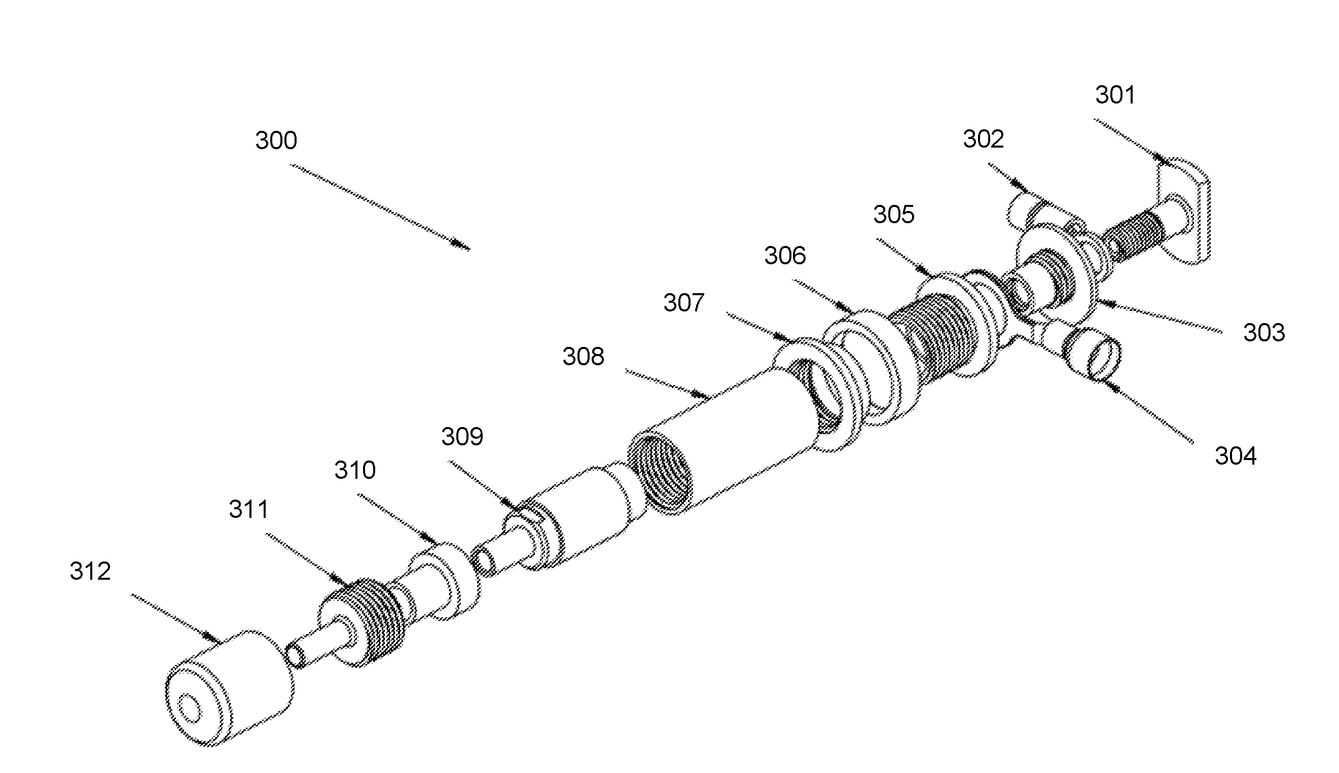
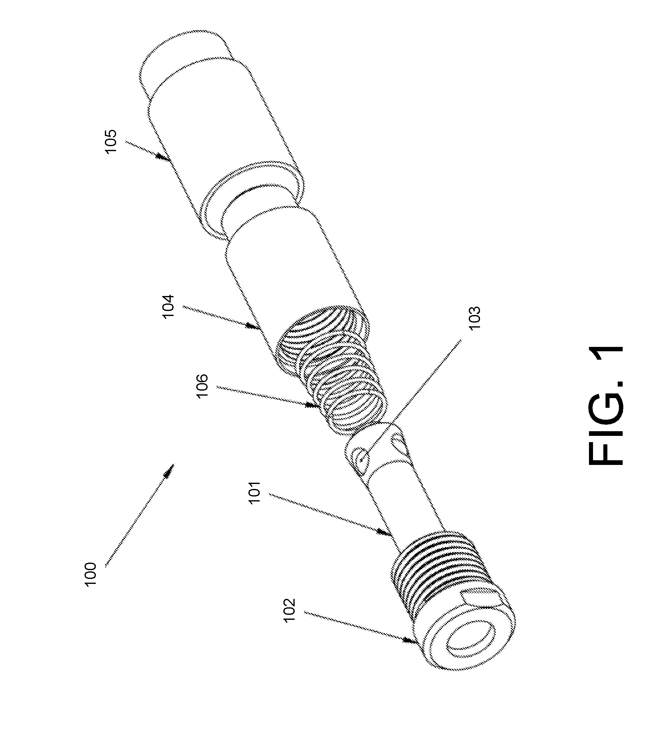
[0016]FIG. 1 depicts an exploded view of an exemplary cable gripper device used in a dual-conductor suspension system for an electrical apparatus.

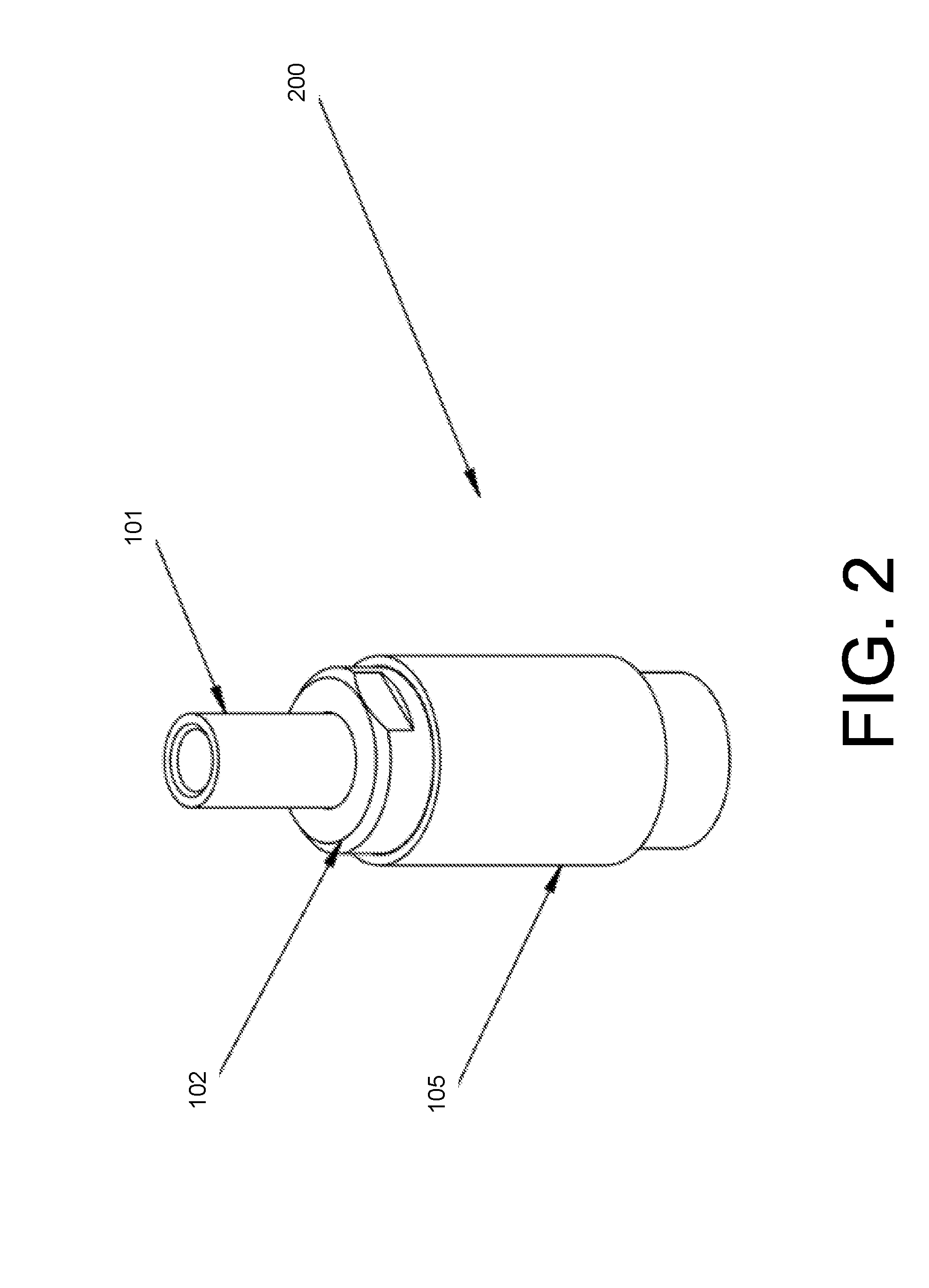
[0017]FIG. 2 depicts an assembled view of an exemplary cable gripper device used in a dual-conductor suspension system for an electrical apparatus.

[0018]FIG. 3 depicts an exploded view of a hardware assembly that may be used to mount to a lighting fixture or other suspended apparatus that requires power.

[0019]FIG. 4 may be the assembled version of a hardware assembly that may be used to mount to a lighting fixture or other suspended apparatus that requires power.

[0020]FIG. 5 is an exploded view of a hardware assembly that may be used to mount to a ceiling a cable that suspends a lighting fixture or other suspended apparatus that requires power.

[0021]FIG. 6 is the assembled version of a hardware assembly that may be used to mount to a ceiling a cable that suspends a lighting fixture or...


PUM

PropertyMeasurementUnit
Heightaaaaaaaaaa
Pressureaaaaaaaaaa
Electrical conductoraaaaaaaaaa

Abstract

A system for suspending and powering an electrically-powered fixture, such as a luminaire, with a coaxial suspension cable, and for attaching the fixture to the cable and to a structure, such as a ceiling, using at least one cable gripping devices, such that the height of the fixture may be adjusted. The suspension cable may comprise an inner cable, which may include a plurality of strength strands wound around a conductive strand; and an outer conductor, such as a copper mesh, separated from the inner cable by an insulator layer. The system may include an assembly mounted to the structure and an assembly mounted to the fixture, each assembly configured to grip the inner cable at one end of the suspension cable and to allow a first conductive path to the inner cable and a second conductive path, insulated from the first conductive path, along the outer conductor.

Description

CROSS-REFERENCE TO RELATED APPLICATION[0001]This application claims the benefit of the following provisional patent applications: U.S. Provisional Application No. 62 / 102,957, filed on Jan. 13, 2015; U.S. Provisional Application No. 62 / 154,241, filed Apr. 29, 2015; and U.S. Provisional Application No. 62 / 260,107, filed Nov. 25, 2015, all of which are incorporated herein by this reference in their entirety.BACKGROUND[0002]Many electrically-powered assemblies and devices, such as luminaire assemblies, are hung from ceilings or other supporting structures. In order for a luminaire assembly to be hung, the weight of the luminaire assembly must be supported from the supporting structure. In addition, in order to provide light, the luminaire assembly must be provided with power.[0003]Many kinds of supports have been developed to suspend luminaire assemblies and to provide them with power. In recent years, conductive suspension cable systems have been developed for suspending and powering l...

Claims


Application Information

Patent Timeline
IPC IPC(8): F21S8/06H02G3/30H01B9/00F21V23/00
CPCF21S8/06F21V23/002F21Y2101/02H01B9/008H02G3/30F21V21/104F21V21/112F21V23/001F21Y2115/10H02G3/0675H02G3/083
Inventor KWAST, RYANNAPIER, HUGO
Owner GRIPLOCK SYST
Why Eureka
Try Eureka