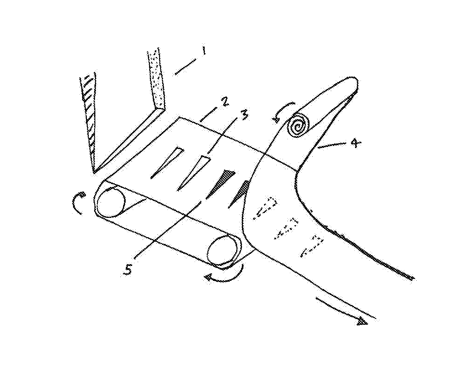
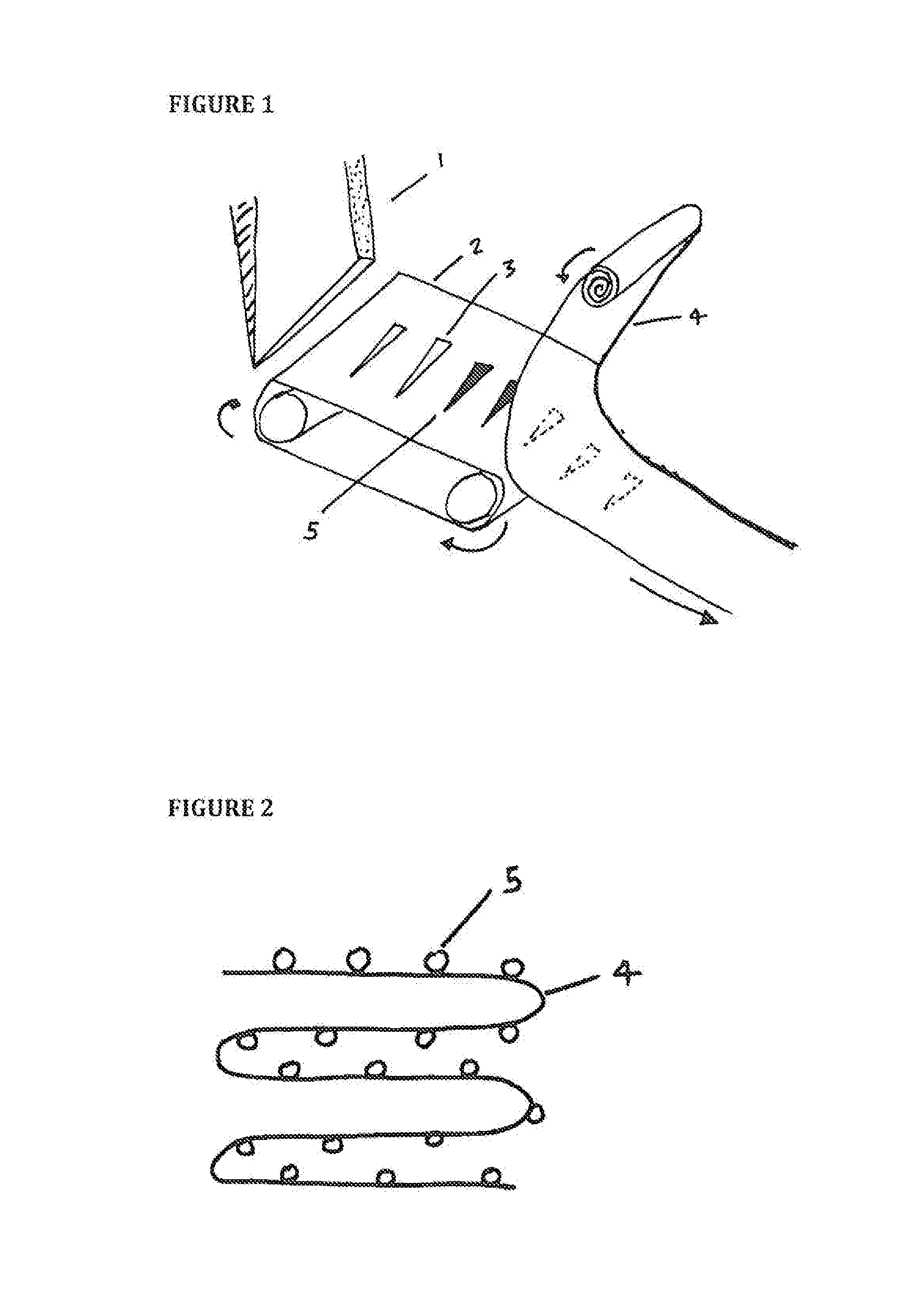
[0021]Referring now to the drawings, FIG. 1 shows a hopper 1 as a source of microneedles designed to feed the needles 5 in a specific orientation, on to a belt 2 with grooves 3. A separate adhesive roll, or substrate 4, makes surface-contact, or near surface-contact, and as a result adheres the needles 5 to the adhesive substrate 4 (as shown by the dotted lines to denote needles 5 adhered to the underside of the adhesive substrate 4). The hopper 1 has an opening that supplies needles 5 which are uniform and/or tapered at both ends. The belt 2 has a plurality of grooves 3 or slots into which the needles 5 are placed. The belt 2 is formed from metal, plastic or rubber. The needles 5 are not required to fit tightly in the grooves 3. While the belt 2 is shown in a horizontal configuration, it may also be inclined laterally at an appropriate angle to allow the tips of the needles 5 to rest against an adjacent wall (not shown) under the influence of gravity. This allows a uniform height of needle 5 to be achieved at the outer surface of the arrays, i.e. the face from which the needles 5 protrude from the final device. The substrate 4 is formed from foam or any standard tape material. If desired the substrate 4 need not be adhesive and may instead contain grooves or slots into which the needles 5 are directly placed, positioned and mechanically restrained before being wound together to form the desired needle array. A mechanical restraint could be a click lock slot that allows needles 5 to be clicked into position.
[0022]FIG. 2 shows a view in cross-section of an embodiment of the invention in which the needles 5 on the tape 4 can be shaped to produce an array, in a rectangular shape. The adhesive (not shown) may be single sided or it may be double sided. The thickness of the adhesive is used to ensure any gaps between the needle 5 and the adhesive is filled by adhesive flow. In its simplest form the needle array may be a single needle 5, or a single row of needles 5, arranged on a substrate 4 which conforms to a particular device housing, e.g., straight, circular, etc. Any gaps between the adhesive and the substrate 4 and the needles 5 are also filled using an insert to cover the edges of the substrate 4, or using silicone or another material that can be applied in liquid form which then solidifies, thus sealing out of sight the needle 5/substrate 4 edges that would otherwise be visible from the bottom face of the array. In the case of tapered needles 5, the tapered portion is generally very close to the tip. However where the tapered portion is along part of the length or the entire length of the needle 5 the upper portion, or the straight portion of the needles, are compressed or held together using an additional material such as a resin. Alternatively, they can be held by mechanical compression, for example, by applying tension on the adhesive substrate upper end to keep the needles 5 straight and prevent them from tapering inwards within the array.
[0023]FIG. 3 shows a view in cross-section of an alternative embodiment of the invention in which the needle 5 loaded substrate 4 is wound around a core 6 or around itself in a spiral configuration to form an array. The needle 5 loaded substrate 4 is wound around the core 6 until a desired diameter of device is achieved.
[0024]FIG. 4 is a schematic of the needles 5 adhered or connected to the substrate 4 leaving the upper 7 and lower 8 portions of the needles 5 exposed. In doing this the upper ends 7 of the needles 5 can be enclosed into a housing of the device and may further be secured using chemical or mechanical restraint means. For example, using resin or an adhesive mass that sets into a solid, preventing movement of the needles 5 in the lateral direction, and preventing the needles 5 from slipping out of the array where the needles 5 may be pierced into a hard material that offers resistance when pulling the needle array away from the surface. A significant benefit of using an adhesive based substrate 4 is that very large forces will be required to dislodge the needles 5 from the device due to the high surface area of contact between needle surface 5 and adhesive. Furthermore shear forces required to slide the needle 5 away from the adhesive are significantly higher than those required to peel the needle 5 from the adhesive, and by wrapping the needles 5 on themselves tension may be applied to provide additional compression on the adhesive and needle wall surfaces. Allowing the lower portion 8 of the needles 5 to be exposed further than their desired finished length will allow for a ‘spacer’ to be attached to adjust the height of the protruding portion of the needles5 as required—or indeed for mechanically adjusting the height of the needles 5 protruding from the lower face using a mechanical screw for example to adjust the height.
[0025]FIG. 5 shows the substrate 4 wound or folded into a rectangle, with the lower portions 8 of the needles protruding from the base of the array, and the upper portions 7 of the needles protruding from the top of the array. The upper portions 7 are partially encased within a resin 10 or some other material to stabilize the needle array. The dotted lines 9 represent an optional electrical contact means to each individual needle via the upper portions 7 of the needles 5.
[0026]Microneedles 5 currently available on the market in either stamp like devices, such as dermapads available from Dermaroller®, or other roller devices have a pitch in the region of 1.5 mm from needle tip to tip for needles 5 with a diameter of 250-450 um. Assuming a 450 um diameter, this implies the distance between needle 5 walls is approximately 1 mm, or 1.25 mm in the case of 250 um diameter needles 5. This invention allows the needle 5 to be located on to a substrate 4 as thin as a few microns, thus achieving a pitch that is comparable to or smaller than that achieved using injection molding and micro-fabrication techniques, providing a significantly higher density of needles 5 which has very important applications for both drug delivery and diagnostic applications; the pitch may be as low as the diameter of the needle 5 plus the thickness of the adhesive/substrate 4. At one extreme where the substrate 4 is folded in on itself and the needles 5 are touching, the pitch is reduced to the diameter of the needles 5 at their widest point, i.e., the needles 5 would be touching thus the radius of each needle 5 at the widest region separates the needles 5, hence the pitch is equal to the needle 5 diameter at the widest point, or less in the case where the needles 5 are pointed towards each other.
[0027]In the case of diagnostic applications, a suitably designed printed circuit board could be mounted at the base of the upper part of the needle arrays (seated within the housing of a device for example) providing electrical contact and feedback/communication to and from individual needles 5 if desired. This is very difficult or impossible to achieve where needles 5 are micro-metal molded for example as the base of the needle 5 is the same substrate as the needles 5 themselves thus electrically connected as a single unit, rather than individual needle arrays.