

Device for the generative manufacturing of three-dimensional components
a technology of three-dimensional components and generative manufacturing, which is applied in the direction of additive manufacturing processes, manufacturing tools, and applying layer means, etc., can solve the problems of long time between the creation and the overall time for the manufacture of a product cannot be significantly reduced, so as to achieve efficient and cost-effective operation, facilitate the separation of products, and efficient device form
- Summary
- Abstract
- Description
- Claims
- Application Information
AI Technical Summary
Benefits of technology
Problems solved by technology
Method used
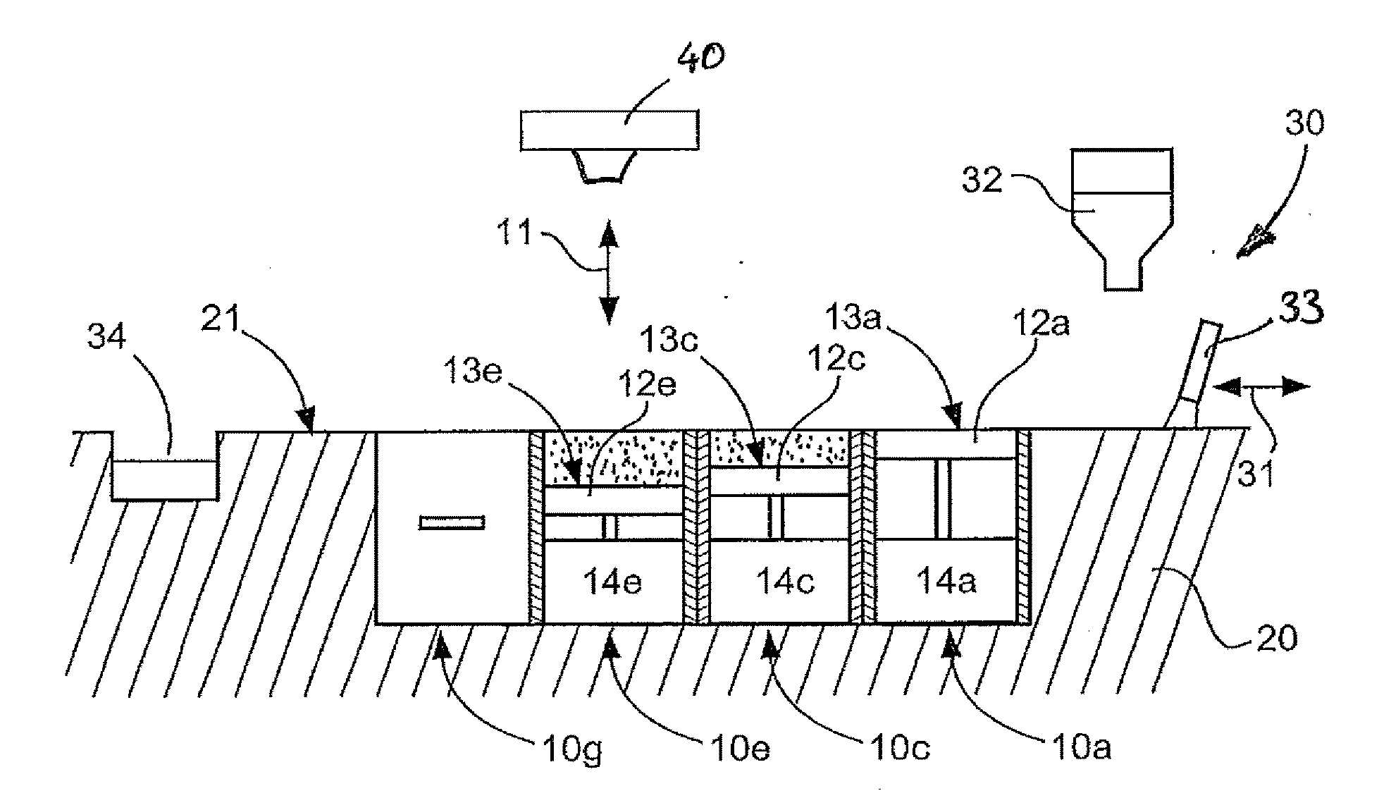
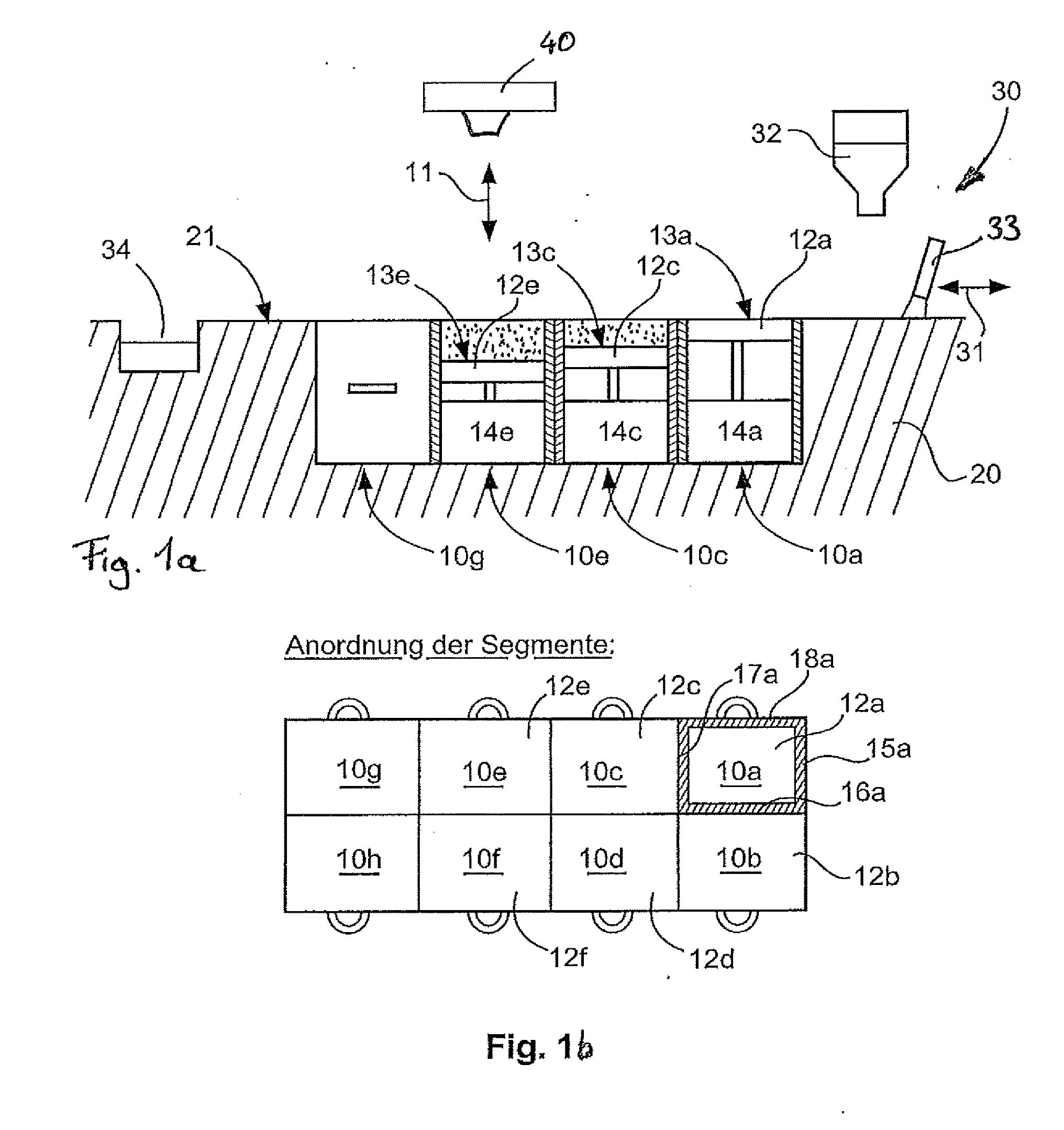
Image

Examples
second embodiment
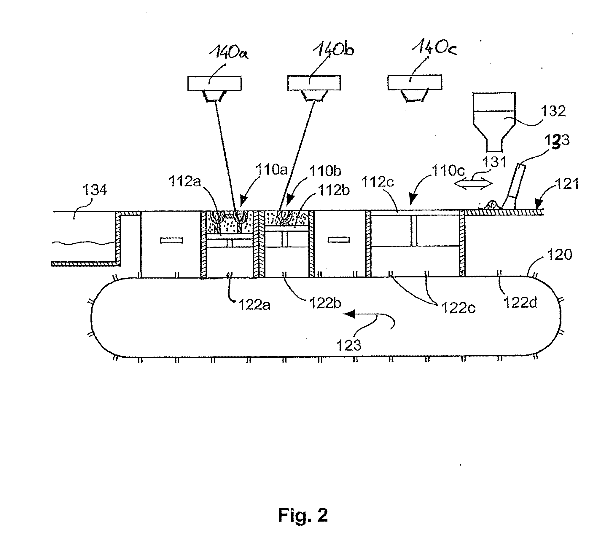
[0198]FIG. 2 shows the invention in which several substrate plate stacks 112a-c can be coupled to an endless conveyor belt 120 as modules 110a-c. Several coupling points 122a, b, c, d . . . are provided on the conveyor belt 120 which also serve as an fixing device for a module 110a-c and provide power supply for an actuator 114a-c included in the module.
[0199]The actuator within each module is designed so that each substrate plate stack 112a-c can be adjusted in height individually.
[0200]As can be seen in FIG. 2, the substrate plate stacks 112a and 112b are designed as individual stacks, while the substrate plate stack 112c is designed as a twin-stack and covers twice the length along the conveyor belt 120.
[0201]Each module 110a-c is fitted with side walls, like the inserts in accordance with FIG. 1A, B, within which the substrate plate stacks 112a-c can move vertically with edges sealed. The upper edge of the edge walls close flush with a surface 121 from which a powder conveyer 13...
seventh embodiment
[0234]FIG. 7 shows the invention. The embodiment has an endless conveyor belt 620 along which several substrate plate stacks 612a-e are located in the direction of conveyance 621.
[0235]The substrate plate stacks 612a-e are positioned so that their top surface is on one plane.
[0236]Above the substrate plate stacks 612a-e, several coating devices 630a-d are positioned. The individual coating devices 630a-d each comprises a coater 633a-d. The bottom edge of the coater 633a is positioned at the distance of a layer from the surface of the substrate plate stacks 612a-e. The bottom edge of the coater 633b is distanced one shift distance more from the surface of the substrate plate stack 612a-e compared to the pervious coater 633a, and in the same way the bottom edges of coater 633c, d are raised appropriately one layer depth more from the surface of the substrate plate stack compared to the previous, adjacent coater.
[0237]The embodiment shown in FIG. 7 displays a range of adjacently positi...
PUM
| Property | Measurement | Unit |
|---|---|---|
| thickness | aaaaa | aaaaa |
| thickness | aaaaa | aaaaa |
| angle | aaaaa | aaaaa |
Abstract
Description
Claims
Application Information