
Tire Vulcanization Bladder and Pneumatic Tire Manufacturing Method

a technology of pneumatic tire and vulcanization bladder, which is applied in the direction of tires, domestic applications, other domestic articles, etc., can solve the problems of difficult to apply the appropriate pressure in accordance with the inner surface shape of each location of the tire being manufactured, and the thickness of the manufactured tire is not the same as the setting, so as to achieve the effect of reducing the number of vulcanization bladders

Inactive Publication Date: 2016-07-28
THE YOKOHAMA RUBBER CO LTD
View PDF1 Cites 1 Cited by
  • Summary
  • Abstract
  • Description
  • Claims
  • Application Information

AI Technical Summary

Benefits of technology

The present invention relates to a vulcanization bladder for tire manufacturing. The invention provides a vulcanization bladder with a constant thickness and specific ribs or grooves on its inner surface that correspond to the tire's tread, shoulder, and bead portions. By adjusting the thickness and spacing of the ribs or grooves, the stiffness of the bladder can be controlled in the desired direction. This allows for appropriate pressure application to the green tire during vulcanization, reducing movement in the tire and ensuring uniform rubber thickness. The invention also provides a specific configuration for the ribs and grooves to minimize the effect of thermal conductance and ensure uniform pressure distribution.

Problems solved by technology

As a result, when pressure is applied to the green tire by the vulcanization bladder, the unvulcanized rubber moves from the portions where the applied pressure is large towards the portions where it is small, which produces the problem that the rubber thickness of the manufactured tire is not same as the setting.
However, stiffness in the portions where the reinforcement reduction member or the reinforcing layer are provided is increased in all directions, not just circumferential stiffness, so it is difficult to apply the appropriate pressure in accordance with the inner surface shape of each location of the tire being manufactured.

Method used


Image

  • Tire Vulcanization Bladder and Pneumatic Tire Manufacturing Method
  • Tire Vulcanization Bladder and Pneumatic Tire Manufacturing Method
  • Tire Vulcanization Bladder and Pneumatic Tire Manufacturing Method

Examples


Embodiment Construction

[0025]The following is a description of the tire vulcanization bladder and a pneumatic tire manufacturing method according to the present embodiment based on the embodiments illustrated on the drawings.

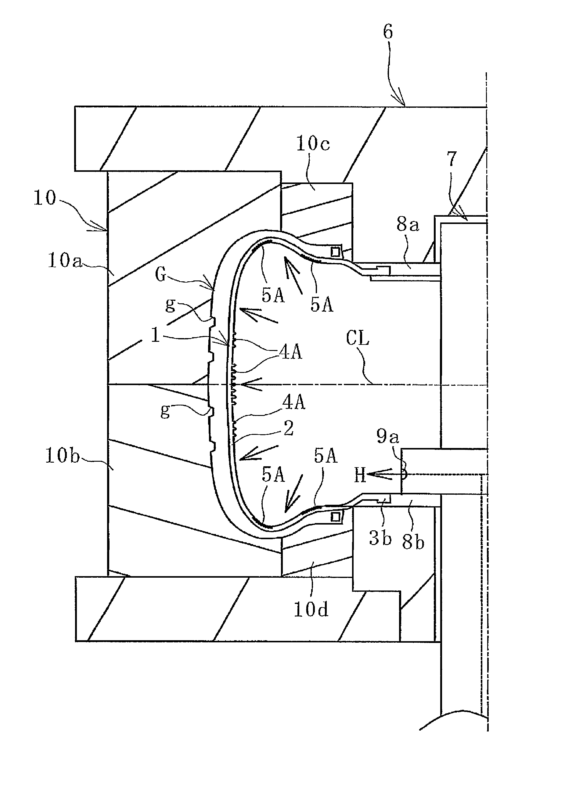
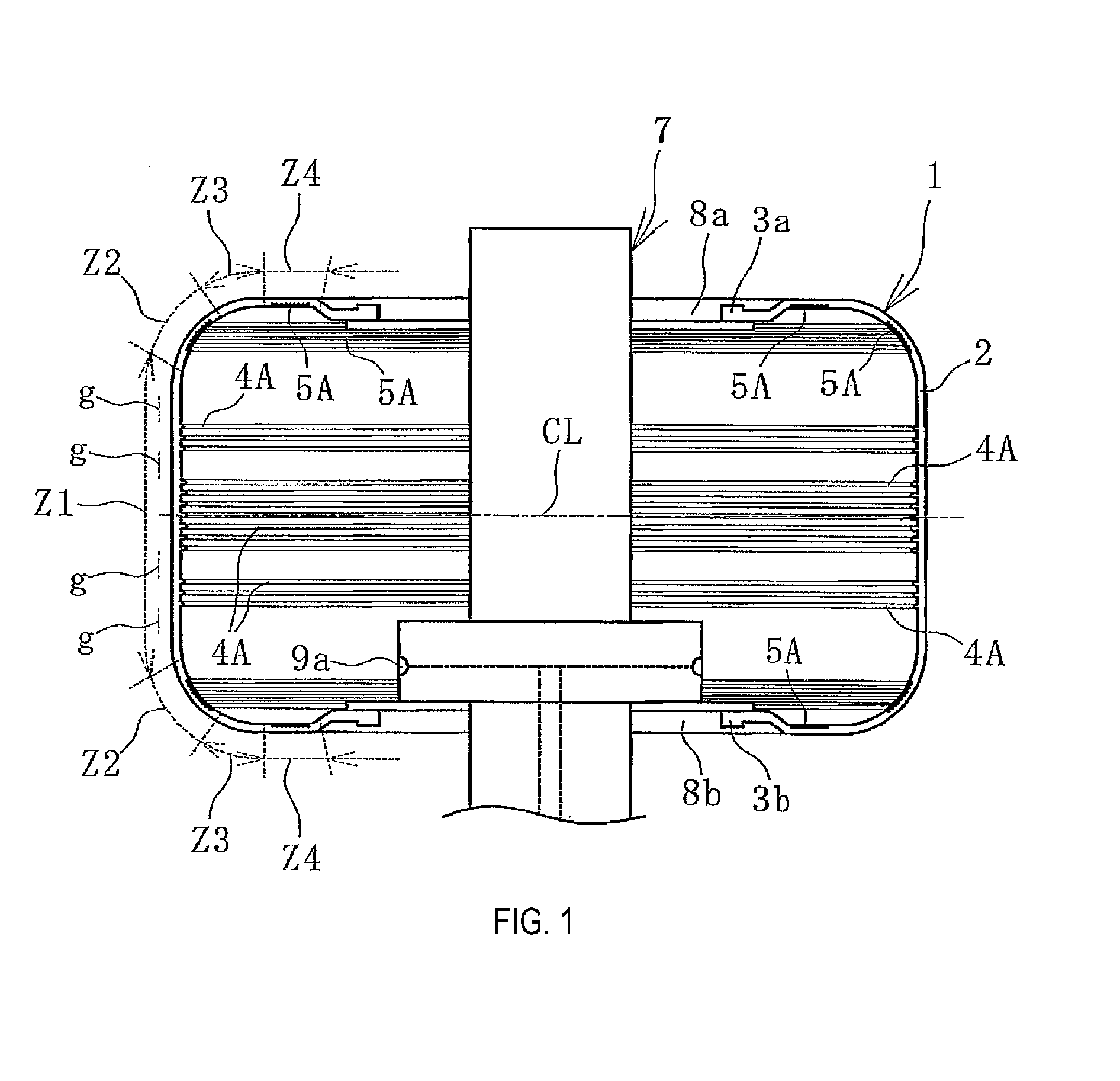
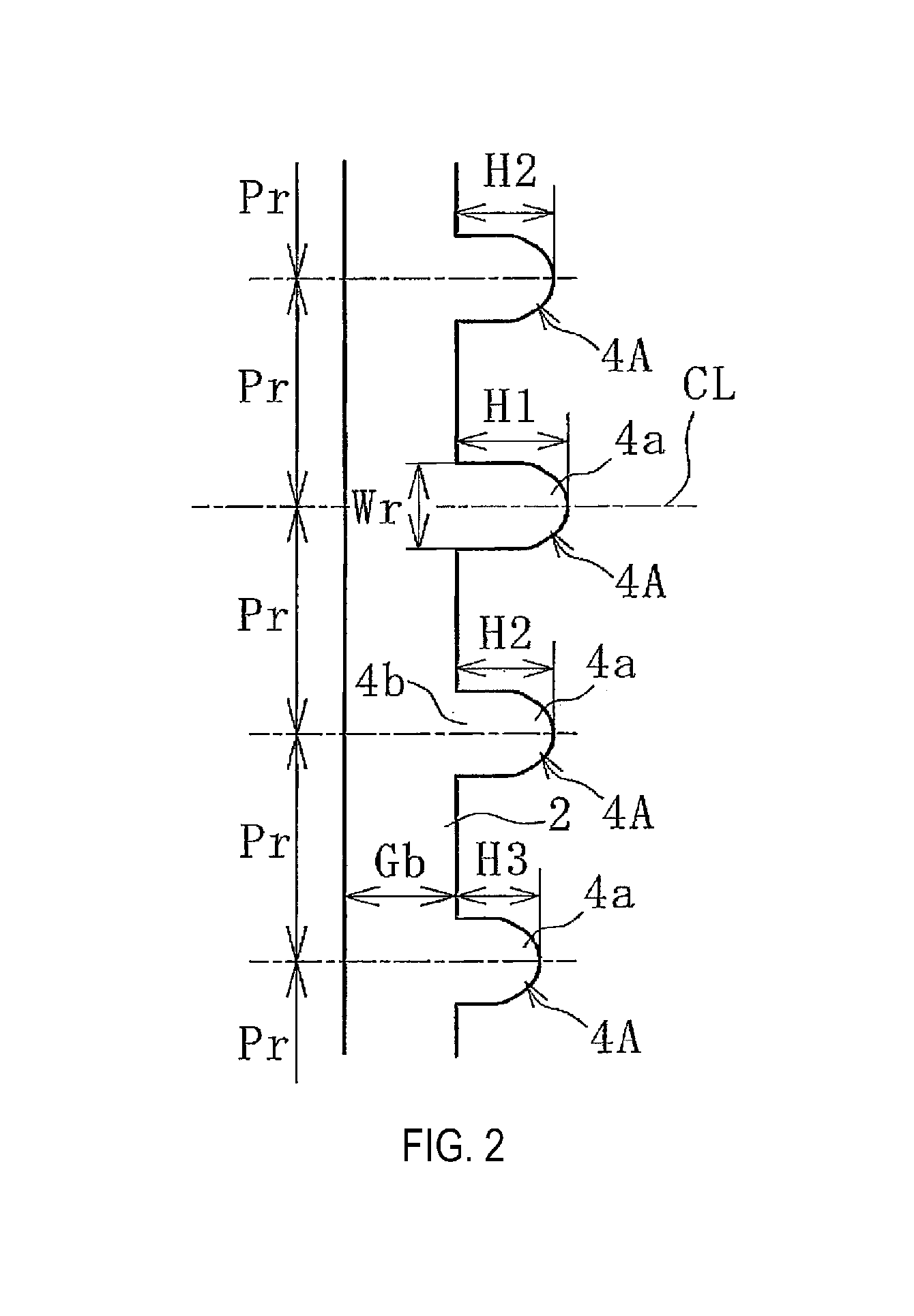
[0026]A tire vulcanization bladder 1 (hereafter referred to as bladder 1) as illustrated in FIGS. 1 to 3 is made from rubber such as butyl rubber, formed into a cylindrical shape. The thickness Gb of a bladder main body portion 2 is a predetermined constant thickness, and at the two end portions in the cylinder axial direction (opening end portions), a top side clamp portion 3a and a bottom side clamp portion 3b are provided that are formed thicker than the thickness Gb of the bladder main body portion 2. The thickness Gb varies depending on the size of the tire, but for example is about 4 mm to 20 mm. Note that the “constant” in the constant thickness of the thickness Gb includes for a certain percentage of variation that normally occurs in bladders.

[0027]The bladder 1 is installed i...


PUM

PropertyMeasurementUnit
sizeaaaaaaaaaa
degree of freedomaaaaaaaaaa
thicknessaaaaaaaaaa

Abstract

A tire vulcanization bladder where a thickness of a bladder main body portion is set to a constant thickness. At least one of multiple circular ribs, helical ribs in which multiple circumferential ribs are connected in a helix, multiple circular grooves, or helical grooves in which multiple circumferential grooves are connected in a helix is formed on the inner surface of the bladder at the portions corresponding to the tread portion, the shoulder portions, and the bead portions of the tire. When the bladder is inserted into a green tire that is set in the horizontal state within a mold and expanded, the expansion state of the bladder is regulated to press against the green tire in accordance with the inner surface shape of the tread portion the shoulder portions, and the bead portions.

Description

TECHNICAL FIELD[0001]The present invention relates to a tire vulcanization bladder and a pneumatic tire manufacturing method, and more particularly relates to a tire vulcanization bladder and a pneumatic tire manufacturing method using the tire vulcanization bladder capable of applying the appropriate pressure to a green tire in accordance with the inner surface shape of each part of the tire being manufactured.BACKGROUND[0002]When manufacturing pneumatic tires, a green tire is set in a mold, then a vulcanization bladder is expanded inside the green tire and vulcanization is carried out. The green tire is normally set within the mold in a horizontal state, and the vulcanization bladder is arranged with the cylinder axial direction in the vertical direction. The cylindrical vulcanization bladder normally has a constant thickness (circumferential stiffness is constant in the vertical direction), and top and bottom ends of the bladder are fixed with clamp members and inflated, so the c...

Claims


Application Information

Patent Timeline
Patent Type & Authority Applications(United States)
IPC IPC(8): B29D30/06
CPCB29D2030/0659B29D30/0654B29D2030/0655
Inventor SATOH, HAJIME
Owner THE YOKOHAMA RUBBER CO LTD
Learn More