Seat with ventilative property

a ventilative property and seat technology, applied in the field of seats with ventilative properties, can solve the problems of affecting the quality of seats, affecting the resiliency of seats, and the three-dimensional network cushion element itself being permanently sunk downward, so as to prevent permanent settling and deformation, reduce humidity, and provide sufficient ventilation

Active Publication Date: 2016-08-04
TACHI S CO LTD +1
View PDF12 Cites 5 Cited by
  • Summary
  • Abstract
  • Description
  • Claims
  • Application Information

AI Technical Summary

Benefits of technology

[0017]The present invention therefore can prevent the permanent settling and deformation in this kind of seat, while maintaining sufficient ventilation to reduce humidity therein so that a seat occupant may not become sweaty in the seat.

Problems solved by technology

However, since the three-dimensional network cushion element actually occupies substantive forward region of the seat cushion, it has been found that, during a long period of time in using the seat cushion, the three-dimensional network cushion element becomes low in resiliency due to a weight of seat occupant being repeatedly applied thereto and consequently loses in resilient recovery force for recovering its original shape, which causes a permanent downward settling of the three-dimensional network cushion element itself.
Hence, there have been the following problems: quality degradation of outer appearance of the seat cushion; insufficient reduction of humidity that can not avoid sweaty state of seat occupant's thigh portions; degradation of stable support touch of the seat cushion to the seat occupant; and a short life of ventilation for the seat cushion.

Method used


Image

  • Seat with ventilative property
  • Seat with ventilative property
  • Seat with ventilative property

Examples


Embodiment Construction

[0025]With reference to the annexed drawings, a detailed description will be made of a preferred embodiment of a seat with ventilative property, in accordance with the present invention.

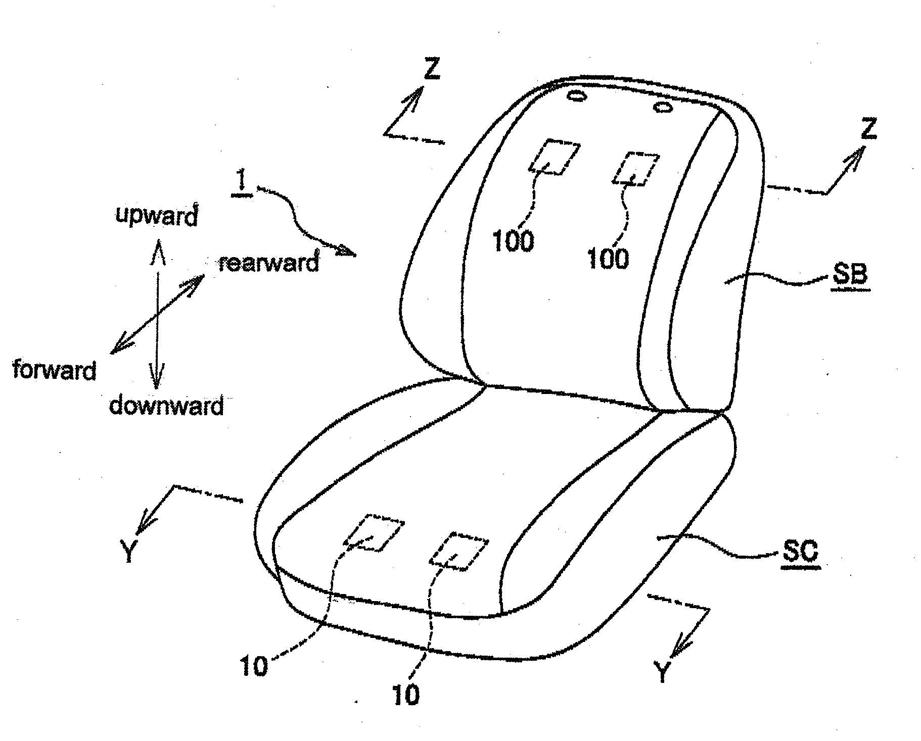
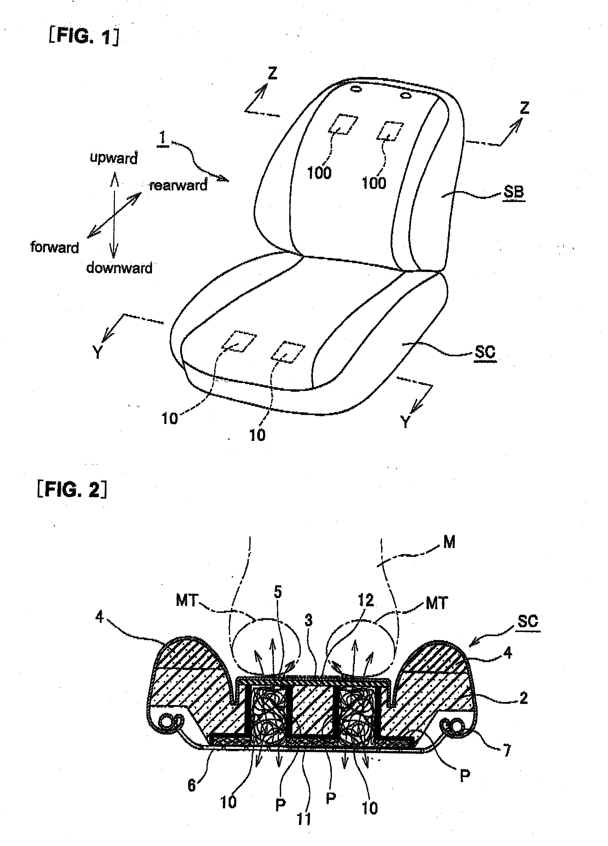
[0026]As shown in FIG. 1, a seat with ventilative property, designated by 1, is comprised of: a ventilative seat cushion SC; and a ventilative seat back SB inclinably connected to the seat cushion SC.

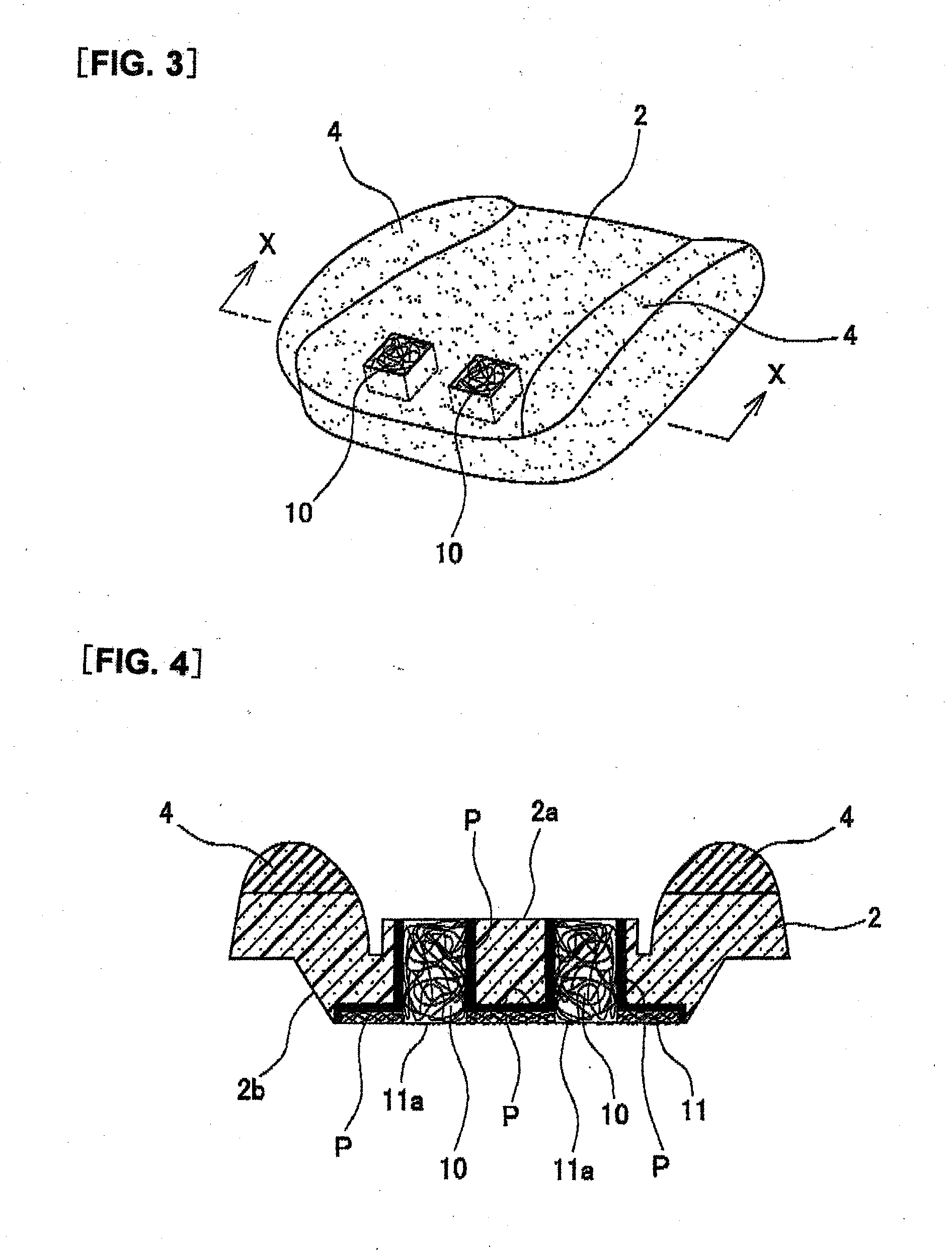
[0027]As shown in FIGS. 2 and 3, the seat cushion SC of the seat 1 includes: a main foam padding portion 2 made of an urethane foam material; and a pair of left and right side support padding portions 4 and 4. Those left and right side support padding portions 4 and 4 are provided to the main foam padding portion 2 in an integral manner and are located at left- and right-side areas of a seating surface 3 of the seat cushion, respectively, so as to protrude upwardly therefrom. Each of the two side support padding portions 4 is formed from a high-density urethane foam material which is large in density rel...


PUM


Abstract

To provide a seat with ventilative property, which can eliminate or minimize the possibility of its being permanently deformed and settled into an unrecoverable deformed state. In the seat with ventilative property, left and right three-dimensional network cushion elements are provided in a forwardly-facing region of a seat cushion of the seat, in a manner independent of each other, such that the left and right three-dimensional network cushion elements are respectively situated at: one location on which a left thigh portion of a seat occupant is to be contacted; and the other location on which a right thigh portion of the seat occupant is to be contacted. This arrangement can almost completely prevent a direct application of a weight of the seat occupant to the two three-dimensional network cushion elements. Therefore, the present invention has the effect that a permanent downward settling of the seat cushion SC can be prevented, so that a short life of the seat due to such permanent settling may be substantially avoided.

Description

TECHNICAL FIELD[0001]The present invention relates to a seat with ventilative property, which is capable of ventilation to avoid a seat occupant becoming sweaty at points where his or her body portion contacts the seat.BACKGROUND ART[0002]Conventionally, in this kind of technical field, for example, a Japanese Laid-Open Patent Publication No. 2012-115515 discloses a seat having a ventilative property, which comprises: an urethane foam padding provided in a seating area of a seat cushion of the seat at a point where a buttocks portion of a seat occupant is to be positioned; and a three-dimensional network cushion element disposed in the seat cushion at another point where two thigh portions of the seat occupant are to be positioned, wherein the three-dimensional network cushion element is formed by entangling fibers with one another in a three-dimensional network fashion. In this prior art, the three-dimensional network cushion element acts to ventilate the seat cushion at the point ...

Claims


Application Information

Patent Timeline
Patent Type & Authority Applications(United States)
IPC IPC(8): A47C7/74A47C7/35A47C7/18
CPCA47C27/22A47C7/18A47C7/40B60N2/7017A47C7/35A47C7/746B60N2/5664B68G11/04A47C31/006
Inventor MIYATA, KEIYOSHIKAWA, JUNPEI
Owner TACHI S CO LTD
Why Eureka
Try Eureka