Air conditioning unit
a technology of air conditioning unit and air intake, which is applied in the direction of vehicle components, vehicle heating/cooling devices, transportation and packaging, etc., can solve the problems of increasing air pressure loss, noise, and similar noise, and achieves the effect of reducing the pressure loss of air drawn by the blower, reducing the transmission of noise, and increasing the suction port area
- Summary
- Abstract
- Description
- Claims
- Application Information
AI Technical Summary
Benefits of technology
Problems solved by technology
Method used
Image
Examples
first embodiment
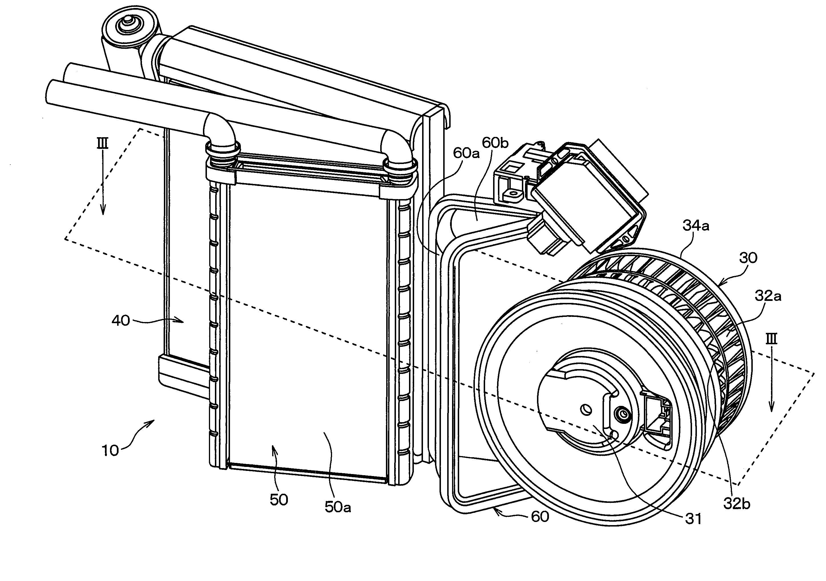
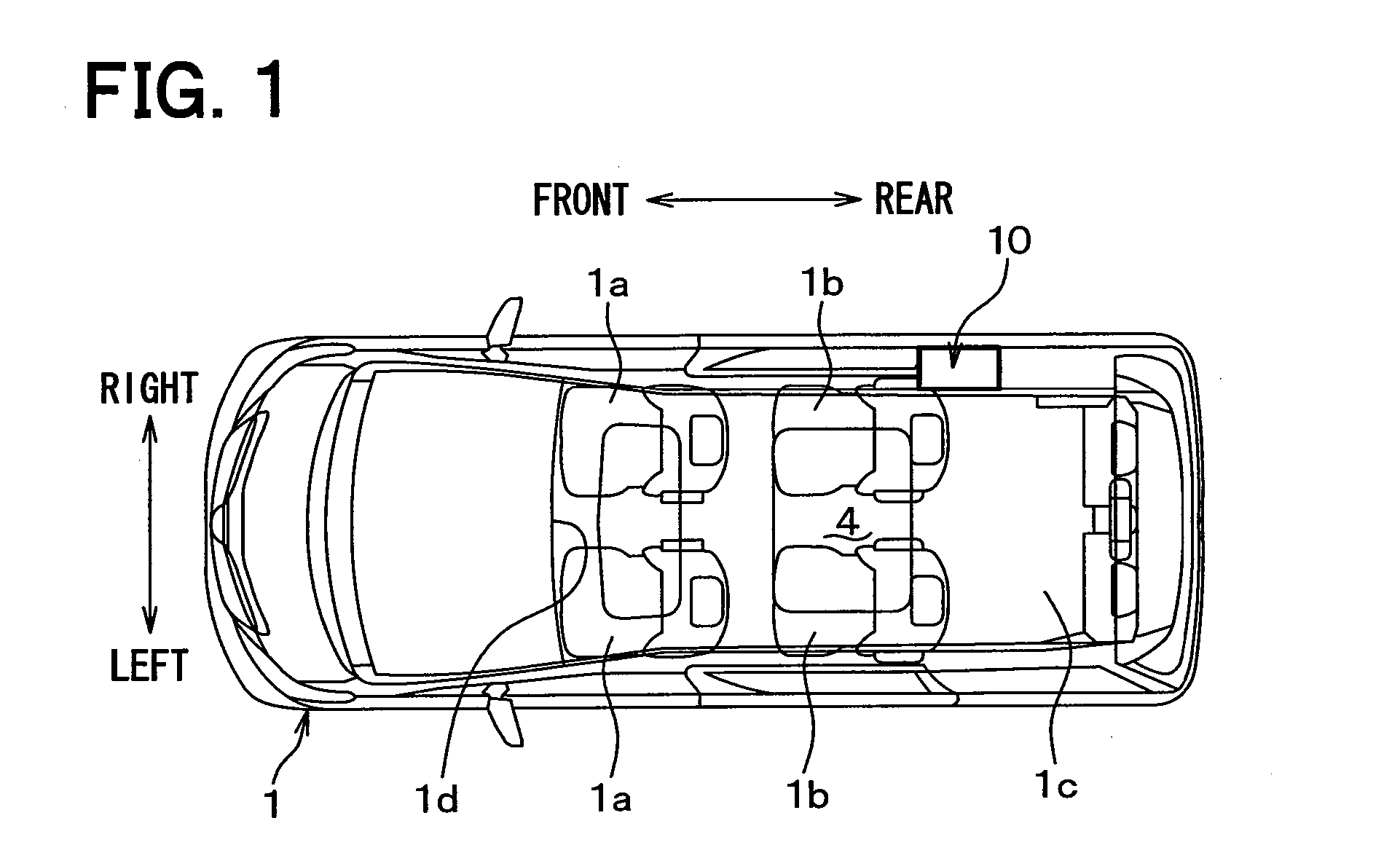
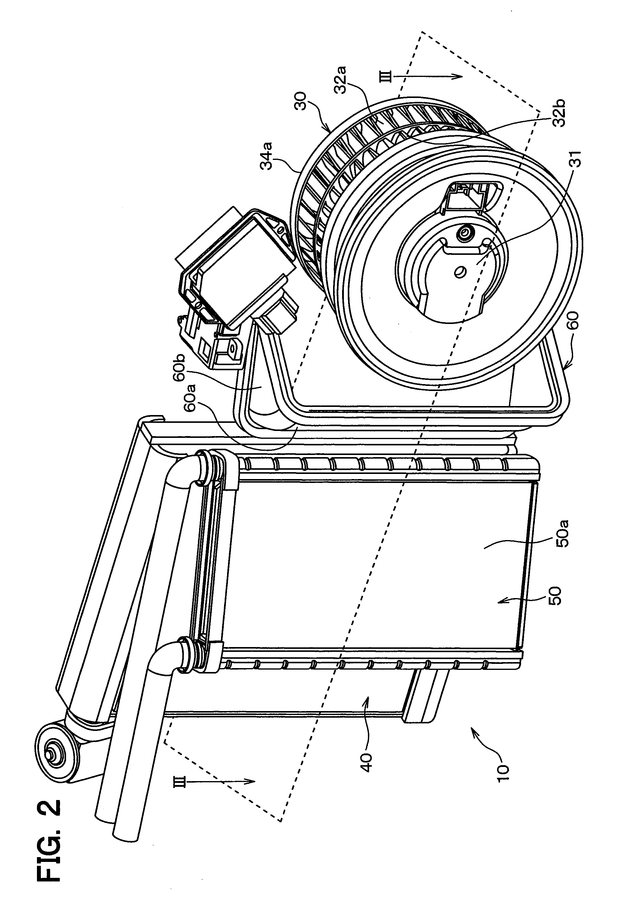
[0023]FIGS. 1, 2, and 3 shows an air conditioner for a vehicle according to the present embodiment of the present disclosure. Arrows in FIGS. 1 and 3 shows directions on a condition of being mounted in the vehicle.
[0024]A vehicle 1 in which the air conditioner for a vehicle is mounted has a rear space 1c in a vehicle compartment on a rear side with respect to a front seat 1a and a rear seat 1b in a traveling direction of the vehicle. The rear space 1c is used to dispose a rearmost seat therein or used as a luggage room.
[0025]The air conditioner for a vehicle of the present embodiment further has an air conditioning unit 10 for a rear seat that performs an air-conditioning of a rear seat side in the vehicle compartment in addition to an air conditioning unit for a front seat (not shown) that performs an air-conditioning of a front seat side in the vehicle compartment.
[0026]The air conditioning unit for a front seat is well-known to be arranged in a substantially center part in a left...
second embodiment
[0062]In the above-described first embodiment, an example in which the evaporator 40 and the heater core 50 are arranged in parallel in a direction intersecting with the airflow direction is described. In an second embodiment, an example in which the evaporator 40 and the heater core 50 are arranged in series in the airflow direction.
[0063]FIG. 4 is a sectional view illustrating an air conditioning unit 10 for a rear seat according to the second embodiment of the present disclosure.
[0064]The air conditioning unit 10 for a rear seat has the air conditioning case 20, the blower 30, and the air mix door 60. In FIG. 4, the same reference numbers as FIG. 2 show the same members, and the explanation is simplified.
[0065]According to the present embodiment, the evaporator 40 is arranged such that the air outlet surface 40a faces leftward. The air outlet surface 40a of the evaporator 40 is arranged to incline with respect to the traveling direction. The heater core 50 is arranged on a downst...
third embodiment
[0076]In the above-described first and second embodiments, the air conditioning unit 10 for a rear seat is arranged between the outer plate 2 and the quarter trim 3. In a third embodiment, an air conditioning unit 10 for a rear seat is arranged between a driver seat (Dr) and a passenger seat (Pa).
[0077]FIG. 5 is a diagram illustrating a condition where an air conditioning unit 10 for a rear seat according to a third embodiment of the present disclosure is mounted in a vehicle. FIG. 5 is an overhead view of the vehicle compartment.
[0078]The air conditioning unit 10 for a rear seat of the present embodiment is arranged on a rear side of the instrument panel 1d. More specifically, the air conditioning unit 10 for a rear seat is arranged between a driver seat 80a and a passenger seat 80b on a front side with respect to the rear seat 80c. The driver seat 80a and the passenger seat 80b are arranged in the left-right direction. The air conditioning unit 10 for a rear seat is arranged insid...
PUM
 Abstract
Description
Claims
Application Information
 - R&D
- Intellectual Property
- Life Sciences
- Materials
- Tech Scout
- Unparalleled Data Quality
- Higher Quality Content
- 60% Fewer Hallucinations
Browse by: Latest US Patents, China's latest patents, Technical Efficacy Thesaurus, Application Domain, Technology Topic, Popular Technical Reports.
© 2025 PatSnap. All rights reserved.Legal|Privacy policy|Modern Slavery Act Transparency Statement|Sitemap|About US| Contact US: help@patsnap.com


