Lighting system and a method of controlling a lighting system

Active Publication Date: 2016-08-04
SIGNIFY HLDG BV
View PDF5 Cites 50 Cited by
  • Summary
  • Abstract
  • Description
  • Claims
  • Application Information

AI Technical Summary

Benefits of technology

[0044]The method can comprise controlling the first lighting unit to have the brightest intensity and controlling other lighting units with reduced intensity in depend

Problems solved by technology

However, many of these solutions do not provide a realistic daylight experience because there is hardly any direct light to provide sharp s

Method used


Image

  • Lighting system and a method of controlling a lighting system
  • Lighting system and a method of controlling a lighting system
  • Lighting system and a method of controlling a lighting system

Examples


Embodiment Construction

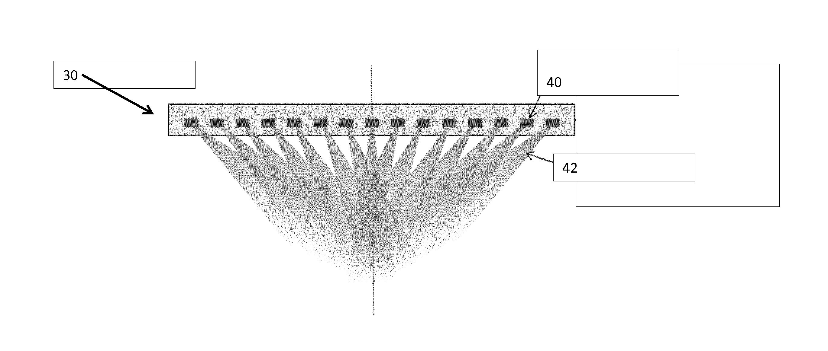
[0054]The invention provides a lighting system which uses an array of lighting elements which provide light in different directions. The intensity of the lighting elements is controlled in dependence on a time-varying parameter which relates to at least one of a position of a light emitting or light reflecting body, and an intensity, color or color temperature of the light emitted or reflected by the body (which can simply be a position corresponding to a determined position of the sun), such that the system simulates directional sunlight.

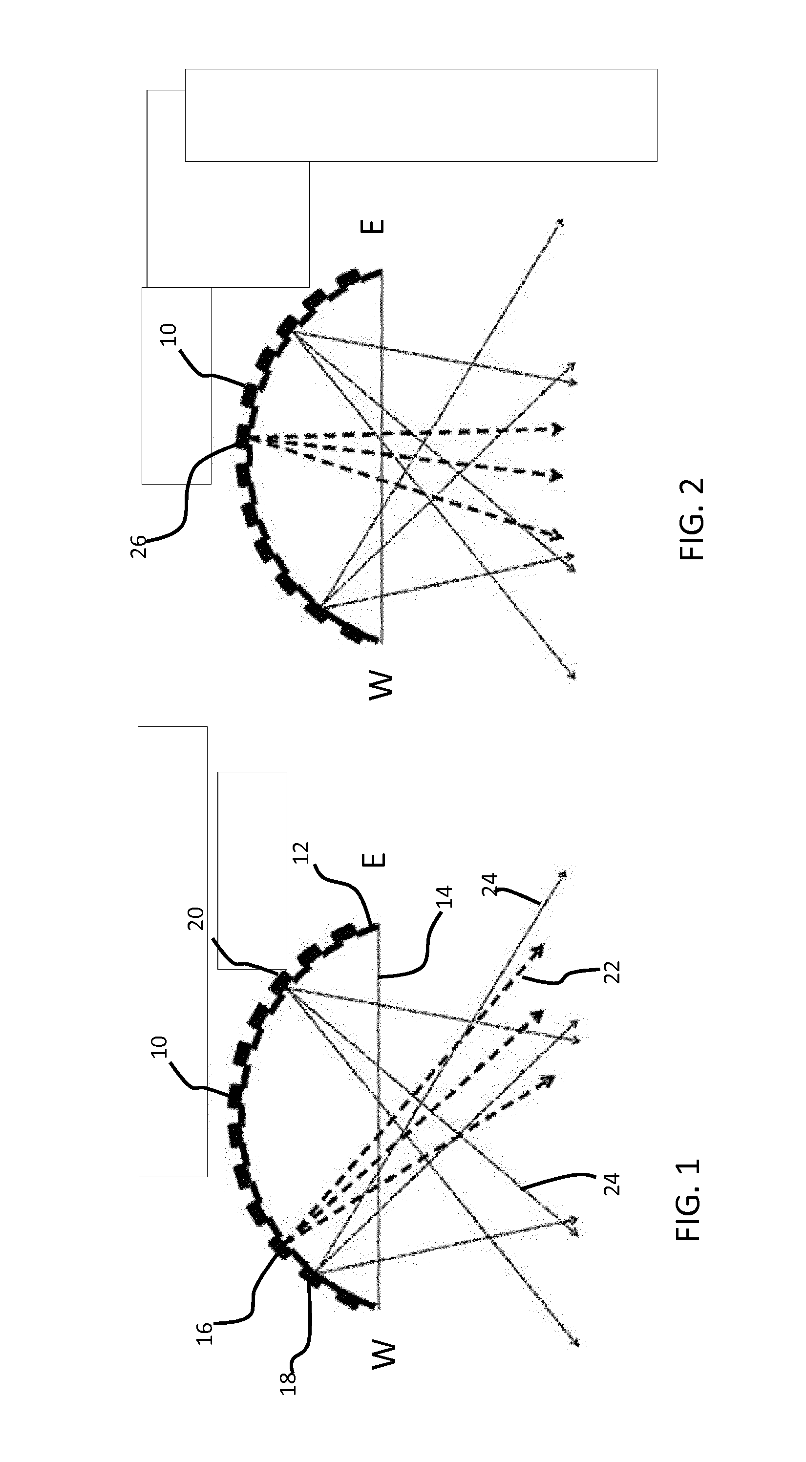
[0055]FIG. 1 shows a first example of lighting system representing early evening daylight. East and west are denoted by E and W. The system comprises an array of lighting elements 10 provided on a convex curved (e.g. spherical) support 12 facing a light output / exit aperture 14. The curvature of the support 12 means that different lighting elements provide light in different directions through the light exit aperture. Each lighting element can provi...


PUM


Abstract

A lighting system uses an array of lighting elements which provide light in different directions. The intensity of the lighting elements is controlled in dependence on a time-varying parameter related to at least one of a position of a light emitting or light reflecting body, and an intensity, color or color temperature of the light emitted or reflected by the body, such that the system can simulate directional sunlight.

Description

FIELD OF THE INVENTION[0001]This invention relates to interior lighting systems.BACKGROUND OF THE INVENTION[0002]People generally prefer daylight over artificial light as their primary source of illumination. Everybody recognizes the importance of daylight in our daily lives. Daylight is known to be important for people's health and well-being.[0003]In general, people spend over 90% of their time indoors, and often away from natural daylight. There is therefore a need for artificial daylight sources that create convincing daylight impressions with artificial light, in environments that lack natural daylight including homes, schools, shops, offices, hospital rooms, and bathrooms.[0004]Artificial daylight sources on the market focus mainly on high intensity, tunable color temperature, and slow dynamics (day / night rhythms). It is also known to create a sky view in a ceiling using a display or foil.[0005]There has been significant development of lighting systems which try to emulate day...

Claims


Application Information

Patent Timeline
IPC IPC(8): H05B33/08F21V5/04F21V14/06H05B37/02F21V7/00H05B44/00
CPCH05B33/0803H05B33/0854H05B33/0866H05B37/0281H05B37/029Y02B20/42F21V7/0091F21V14/06H05B33/0872H05B37/0218F21V5/045F21S10/00F21Y2115/10F21Y2113/17H05B45/24H05B45/10H05B45/00H05B47/16H05B47/155Y02B20/40H05B45/20H05B47/11
Inventor MEERBEEK, BERENT WILLEMVAN GHELUWE, JOCHEN RENAATVAN BOVEN, JACOBUS DINGENIS MACHIELSEUNTIENS, PETRUS JOHANNES HENDRIKUSVAN LOENEN, EVERT JAN
Owner SIGNIFY HLDG BV
Why Eureka
Try Eureka