Determining the size of the air fistula in the thoracic drainage therapy

a technology for determining the size of the air fistula which is applied in the direction of suction devices, intravenous devices, other medical devices, etc., can solve the problems of air accumulation in the pleural space, and no standard treatment recommendations concerning the regulation of the vacuum in the thoracic drainage system, and achieve the effect of optimal treatmen

Inactive Publication Date: 2016-08-11
MEDELA HLDG AG
View PDF5 Cites 2 Cited by
  • Summary
  • Abstract
  • Description
  • Claims
  • Application Information

AI Technical Summary

Benefits of technology

[0019]Thus, the control device takes into consideration both the vacuum and also the volumetric flow in determining the size parameter for the air fistula. In this case, the control device thus mathematically links the measured values of the volumetric flow and of the vacuum to each other, in order thereby to allow a conclusion regarding the functional size of the air fistula. The term “functional size” is to be understood as the effective cross section through which air enters the pleural space. This permits a more exact determination of the size of the air fistula than is possible in methods using solely the pressure or the volumetric flow. This is based on the finding that, with a constant fistula size, a higher vacuum also leads to a higher volumetric flow. By linking the volumetric flow and the vacuum to each other, it is possible to take this relationship into account. In this way, it is possible to calculate a fistula size parameter that is less dependent on the applied vacuum than, for example, the volumetric flow alone.
[0020]Such a determination of a parameter for the size of the air fistula is advantageous even independently of an automatic regulation of the vacuum. Thus, for example, the appliance can have a display device in order to visually present the parameter for the size of the air fistula as a diagnostic parameter (as numbers and / or in graph form). Alternatively or additionally, the appliance can have a memory in order to store the parameter for the size of the air fistula. The appliance can also have an interface in order to read out the parameter for the size of the air fistula. Each of these measures gives the medical personnel in charge of the treatment a more objective view of the course of treatment than is the case in the prior art.
[0029]In this way, a dimensionless indicator F is made available which permits a very simple estimation of the fistula size.
[0033]Whereas in the prior art the level of the aspirating vacuum is generally fixed manually by the physician, it is thus proposed that a suitable parameter indicating the functional size of the air fistula is determined and that the aspirating vacuum is set automatically on the basis of this parameter. By determining a parameter indicating the functional size of the air fistula, the healing process becomes more objective, and, since this size is used to control the suction device, said suction device is controlled automatically on the basis of the objective healing process. In this way, the healing process can be better documented and, in some cases, also made significantly shorter.
[0040]In particular, the control device can increase the vacuum by the first differential value in step (b) and, accordingly, lower the vacuum by the second differential value in step (d) if appropriate. In this case, the appliance therefore automatically monitors, with an adaptive algorithm, whether the air fistula is becoming functionally larger or smaller during application of the vacuum increased by the first differential value. If the parameter indicating the functional size of the air fistula has become greater, the appliance concludes from this that the chosen vacuum value was too high and reduces this value by the second differential value. Otherwise, the vacuum is left unchanged. In this way, air fistulas whose functional size becomes smaller under an increased vacuum (“closing fistulas”) and air fistulas whose size becomes larger under an increased vacuum (“opening fistulas”) can be automatically detected and optimally treated. Alternatively of course, in step (b), the vacuum can also firstly be lowered and, accordingly, increased in step (d) if the air fistula becomes functionally larger during application of the vacuum lowered in step (b).

Problems solved by technology

In patients with defects on the lung surface, air losses in the thorax can occur which lead to the accumulation of air in the pleural space.
At present, however, there are no standard treatment recommendations concerning the regulation of the vacuum in thoracic drainage systems for treating air fistulas.

Method used


Image

  • Determining the size of the air fistula in the thoracic drainage therapy
  • Determining the size of the air fistula in the thoracic drainage therapy
  • Determining the size of the air fistula in the thoracic drainage therapy

Examples


example 1

Closing Fistula

[0091]In a patient 1 with an air fistula, the thoracic drainage system Thopaz™ was used. A vacuum of 10 mbar was initially set. This resulted in a volumetric flow of 100 ml / min. From this, a fistula size F=2.15 was calculated using the above equation (see step 33). The vacuum was then increased by 5 mbar to 15 mbar. After one hour, the volumetric flow was measured again. This was now 120 ml / min. From this, a fistula size F=2.13 was calculated. The fistula had therefore functionally decreased in size. The vacuum of 15 mbar was therefore maintained for a further 3 hours.

example 2

Opening Fistula

[0092]In a patient 2, an initial vacuum of 10 mbar was likewise set. In this patient also, this resulted in a volumetric flow of 100 ml / min, from which a fistula size F=2.15 was calculated. The vacuum was again increased by 5 mbar to 15 mbar, and the volumetric flow was measured after one hour. This was now 240 ml / min, corresponding to a fistula size F=2.56. The vacuum was therefore lowered by 10 mbar to just 5 mbar, and this value was maintained for a further 3 hours.

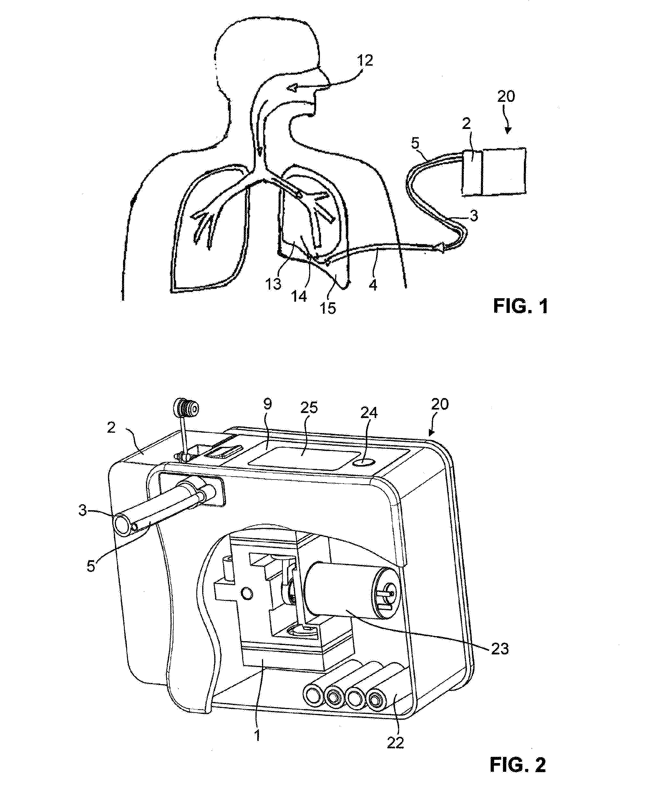
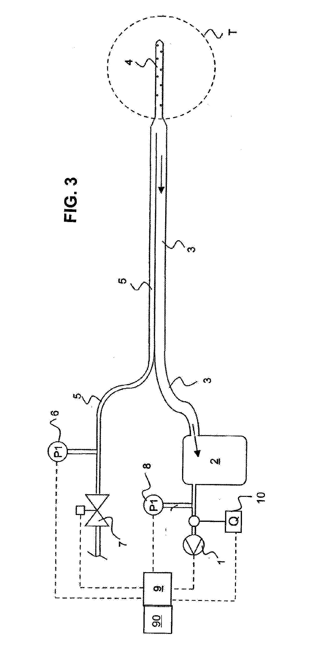
[0093]It is clear that many modifications can be made to the appliances and methods that have been described above by way of example. Thus, the suction device can be any other kind of suction device than the electrical suction pump in FIG. 2, e.g. an attachment for a central hospital vacuum system, as long as the vacuum level can be adjusted by a suitable pressure control. Accordingly, the thoracic drainage system can also be of a completely different construction than that shown in FIGS. 2 and 3. A grea...


PUM


Abstract

Devices and to methods for thoracic drainage for a patient having an air fistula. A vacuum is produced in the pleural cavity of the patient by means of a suction device. In order to adjust the vacuum on the basis of objective criteria, a suitable size measure for the air fistula is determined and the vacuum produced by the suction device is controlled according to said size measure. An adaptive algorithm includes: (a) determining a first value of a size measure for the air fistula; (b) changing the vacuum by a first difference value; (c) determining a second value of the size measure after a first waiting period; (d) changing the vacuum by a second difference value having the opposite sign if the second measure is greater than the first measure; (e) repeating steps (a) to (d) after a second waiting period.

Description

CROSS-REFERENCE TO RELATED APPLICATIONS[0001]The present application is a divisional, under 35 USC §120, of U.S. patent application Ser. No. 14 / 122,406, filed Dec. 16, 2013, which is the United States national phase of International Patent Application No. PCT / CH2012 / 000117, filed May 24, 2012, which application claims priority of Switzerland Application No. 0909 / 11, filed May 27, 2011. The entire text of each of the priority applications is incorporated herein by reference.TECHNICAL FIELD[0002]The present invention relates to an appliance for thoracic drainage and to a corresponding method and computer program.PRIOR ART[0003]In patients with defects on the lung surface, air losses in the thorax can occur which lead to the accumulation of air in the pleural space. A defect that leads to admission of air into the pleural space is generally designated below as an air fistula. Air fistulas are generally treated by thoracic drainage (pleural drainage), in which a vacuum is applied to the...

Claims


Application Information

Patent Timeline
Patent Type & Authority Applications(United States)
IPC IPC(8): A61M1/00A61M1/04
CPCA61M1/0023A61M1/0031A61M1/0088A61M2205/3331A61M2205/3344A61M2210/101A61M1/04A61M2205/3334A61M1/74A61M1/732A61M1/734A61M1/71A61M1/96
Inventor LINDER, ALBERTEHLERT, HILMARWALTI, MARTIN
Owner MEDELA HLDG AG
Why Eureka
Try Eureka