Friction welding

a technology of friction welding and welding ring, which is applied in the direction of turbines, manufacturing tools, mechanical equipment, etc., can solve the problems of inefficient expulsion, preventing or hindering the removal of interfacial contaminants, and the inability to optimize the distribution of energy input into the weld

Active Publication Date: 2016-08-11
ROLLS ROYCE PLC
View PDF14 Cites 5 Cited by
  • Summary
  • Abstract
  • Description
  • Claims
  • Application Information

AI Technical Summary

Benefits of technology

[0016]Advantageously, by providing such channels, flash (i.e. excess material) can be removed more efficiently. In addition, the channels, when formed in the first weld surface, can provide scraping edges to increase frictional contact between the first and second weld surfaces. In this way, the amount of energy needed for conditioning of the interface can be reduced. Additionally, or alternatively, the channels can be used to vary the pattern of energy input into the weld, e.g. to compensate for a bias or asymmetry in input energy distribution caused by workpiece geometry at the weld surfaces, or to compensate for asymmetry in input energy distribution in rotary friction welds where the inside diameters of the weld surfaces are much less than their outside diameters.
[0027]Groups of the channels may be formed at different distances from the first weld surface. In this way, “fresh” channels can be exposed as increasing upset removes the channels at the surface.

Problems solved by technology

A problem can arise, however, that during upsetting the plasticised (liquid or quasi-liquid) material at the interface may not be expelled efficiently as flash, preventing or hindering the removal of interfacial contaminants.
A further problem can arise that the distribution of energy input into the weld may not be optimal.
Although such channels may eventually become filled with removed flash, they can nonetheless usefully control the initial phase of the weld before becoming ineffective.

Method used


Image

  • Friction welding
  • Friction welding
  • Friction welding

Examples


Embodiment Construction

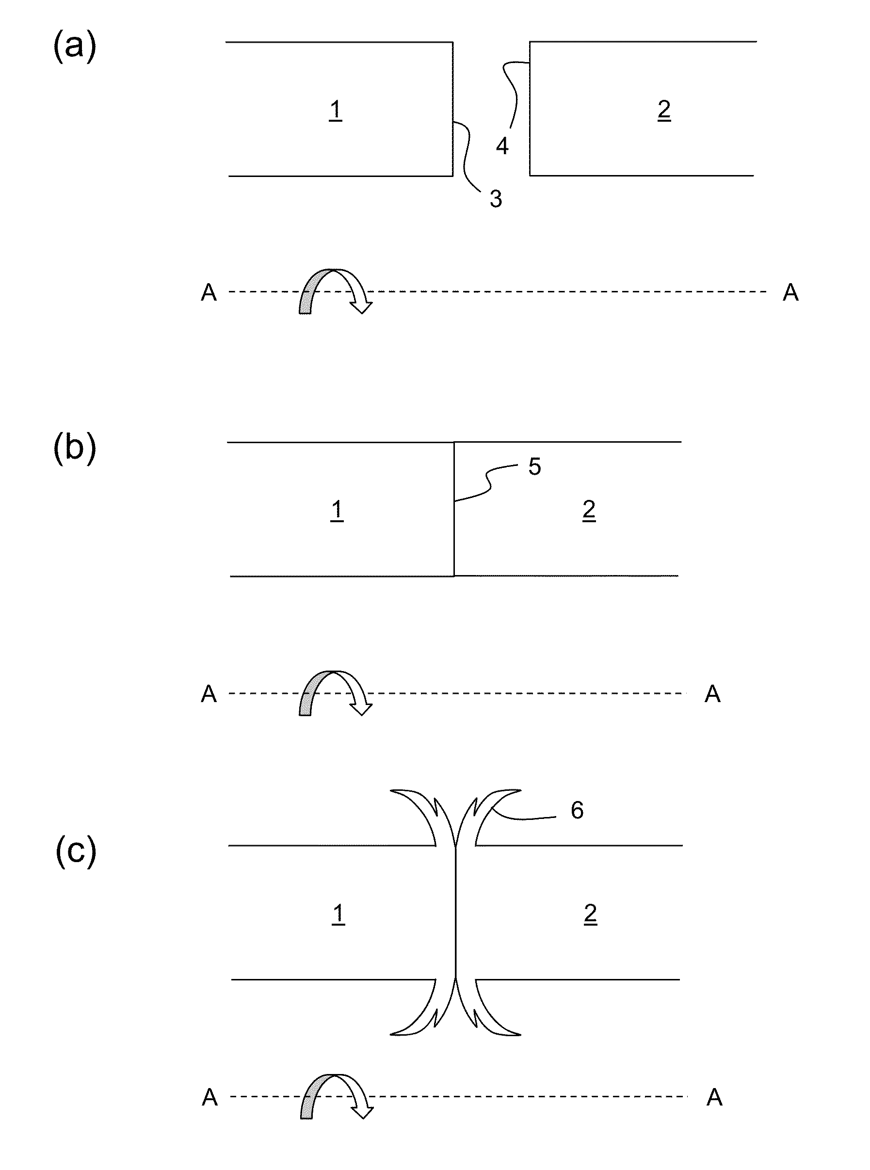
[0036]FIG. 1(a) shows schematically a longitudinal cross-section through a pair of conventional tubular workpieces 1, 2 in readiness to undergo inertia rotary friction welding. The workpieces are aligned on a common axis A-A and have respective end faces forming weld surfaces 3, 4. The left hand workpiece 1 is attached to a flywheel which is rotated at a pre-determined speed, indicated by the solid arrow.

[0037]As shown in FIG. 1(b), the workpieces are brought together so that the weld surfaces 3, 4 make contact. During the conditioning period friction raises the temperature at the weld interface 5.

[0038]When the temperature at the interface 5 is high enough to sufficiently plasticise the material of the workpieces 1, 2, upsetting progressively pushes the workpieces together and flash 6 is expelled sideways from the interface.

[0039]However, the conventional welding process allows undesirable contaminants and other undesirable features to be retained at the weld interface during weldi...


PUM

PropertyMeasurementUnit
anglesaaaaaaaaaa
chevron angleaaaaaaaaaa

Abstract

A friction welding process includes: providing a first workpiece having a first weld surface, and a second workpiece having a second weld surface; aligning the workpieces with the weld surfaces facing each other, moving one workpiece relative to the other workpiece, and engaging the first and second weld surfaces such that the movement raises the temperature at the weld surfaces to create a weld interface; and ceasing the movement and allowing the weld interface to cool to weld the workpieces together at the interface. The first workpiece has a plurality of flash removal channels formed in and / or adjacent to the first weld surface. The channels provide pathways for ejection of material from the weld interface during welding.

Description

CROSS-REFERENCE TO RELATED APPLICATIONS[0001]This application is based upon and claims the benefit of priority from British Patent Application Number 1501884.9 filed 5 Feb. 2015, the entire contents of which are incorporated by reference.BACKGROUND[0002]1. Field of the Disclosure[0003]Friction welding is the process for welding together two bodies or workpieces by converting mechanical energy to heat energy by the friction between the engaging weld surfaces of the two workpieces.[0004]2. Description of the Related Art[0005]In rotary friction welding, the process involves effecting relative rotation between the two workpieces while the weld surfaces remain in engagement with each other. In linear friction welding, the process involves effecting relative lateral oscillation between the two workpieces while the weld surfaces remain in engagement with each other.[0006]For example, in inertia rotary friction welding one of two coaxial workpieces is attached to a flywheel, rotated to a pr...

Claims


Application Information

Patent Timeline
Patent Type & Authority Applications(United States)
IPC IPC(8): B23K20/12
CPCB23K20/028B23K20/1205B23K20/129B23K20/122B23K33/00B23K2201/001B23K20/24B23K2101/001
Inventor BRAY, SIMON E.WALPOLE, ANDREW R.
Owner ROLLS ROYCE PLC
Why Eureka
Try Eureka