Protection system of a railway vehicle traction system, associated transmission line and associated railway vehicle
- Summary
- Abstract
- Description
- Claims
- Application Information
AI Technical Summary
Benefits of technology
Problems solved by technology
Method used
Image

Examples
first embodiment
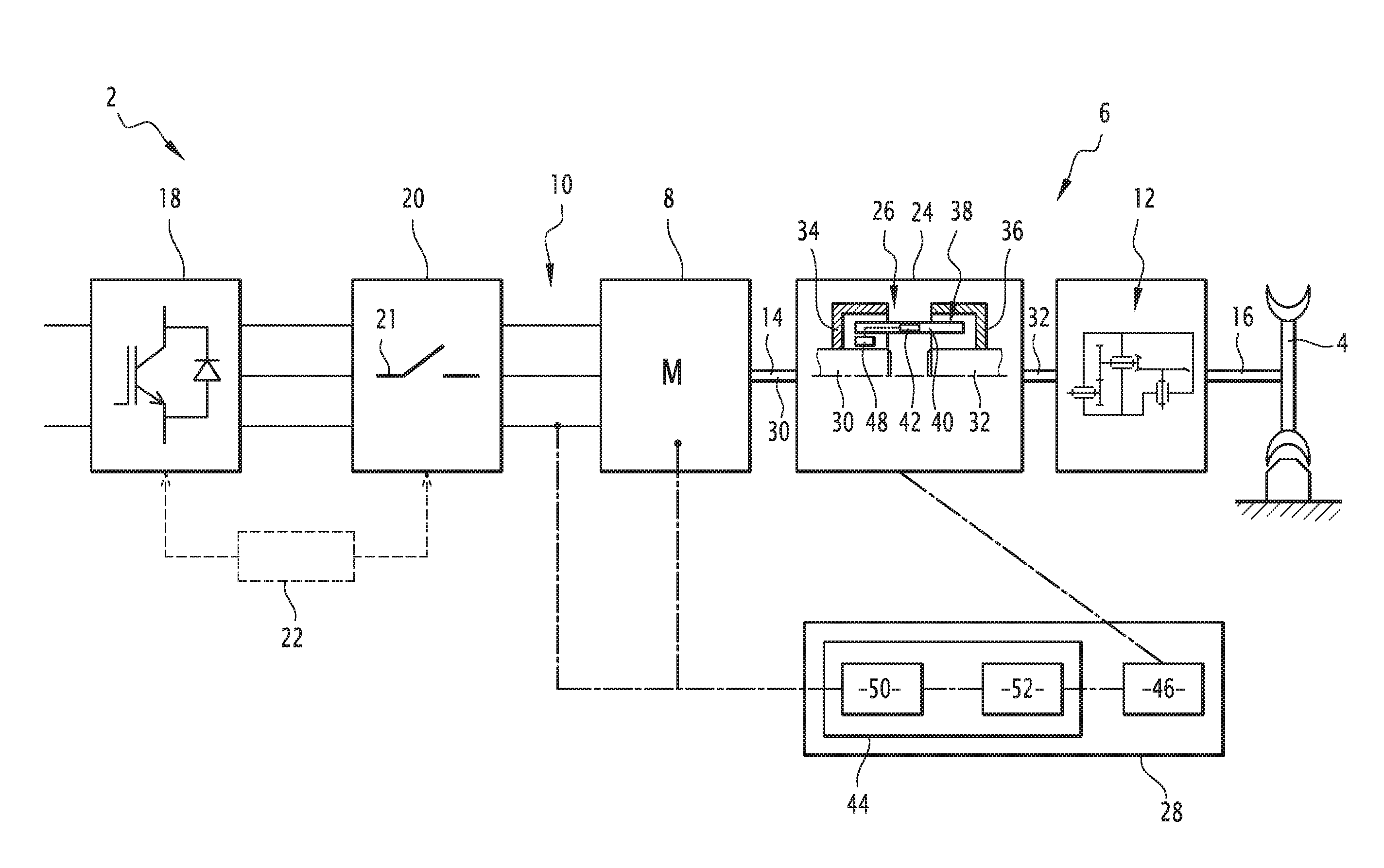
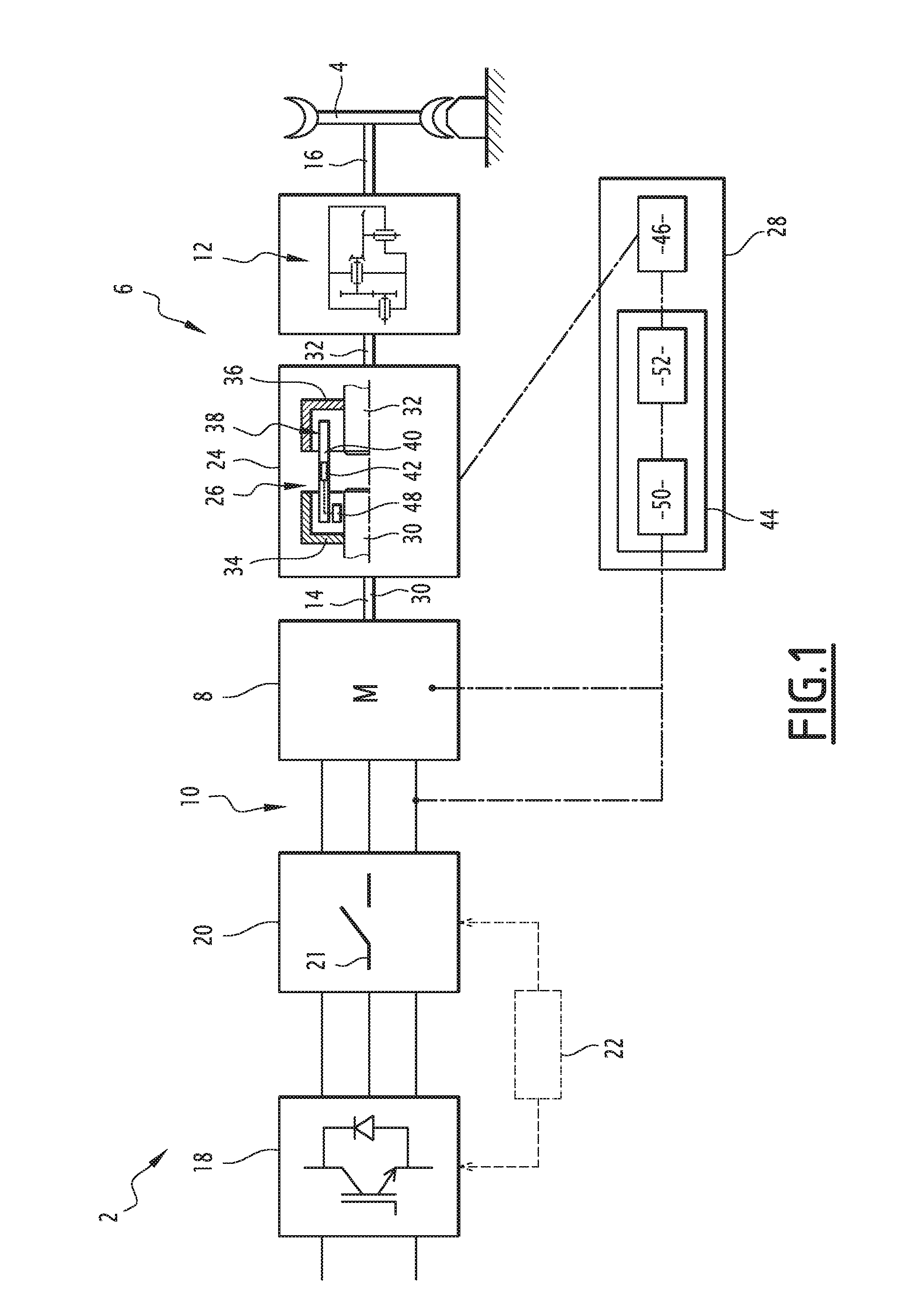
[0032]FIG. 1 shows a traction system 2.
[0033]The system includes an axle 4, a transmission line 6, a permanent magnet motor 8 and an electric power circuit 10 of the motor.
[0034]The motor 8 is a permanent magnet synchronous motor.
[0035]The axle 4 is an assembly made up of a pin secured to at least one pair of wheels, which are guided on a pair of rails.
[0036]The transmission line 6 comprises a reduction gear 12, with one or more stages, positioned between an output shaft 14 of the motor 8 and an input shaft 16 of the axle 4.
[0037]The electric power circuit 10 includes an inverter 18, an insulating contactor 20, a switch 21 for dead short-circuiting of the phases of the motor, and a controller 22 controlling the contactor 20 and the switch 21.
[0038]The inverter 18 includes three output terminals. Each terminal is connected to a phase of the electric motor 8 through the insulating contactor 20, the switch 21, by a connecting cable.
[0039]The controller 22 is able to detect a failure, i...
second embodiment
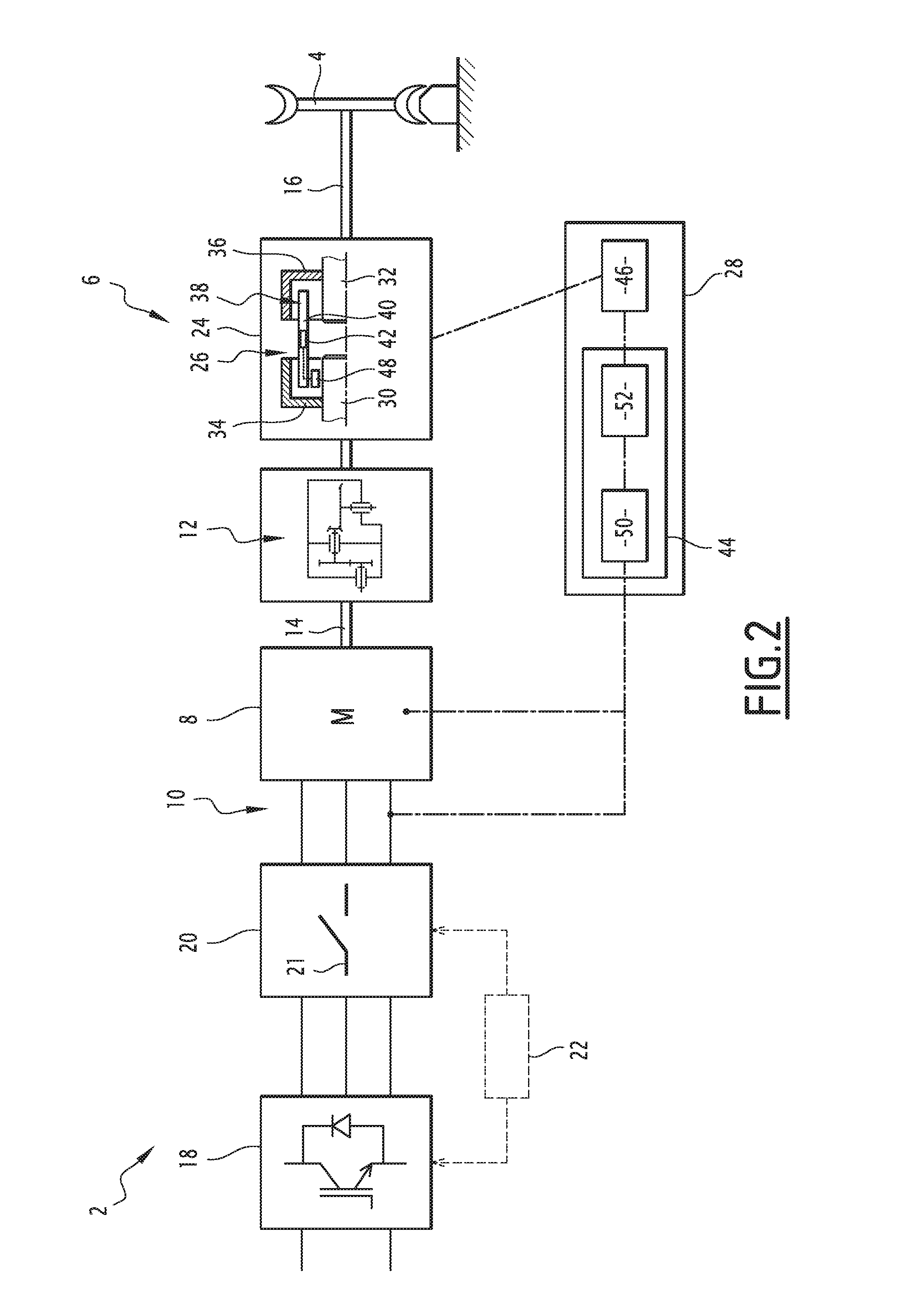
[0084]FIG. 2 illustrates the protection system 24 in which, all other things being equal, the coupler 26 is placed between an output shaft of the reduction gear 12 and an input shaft 16 of the axle.
third embodiment
[0085]FIG. 3 illustrates the protection system 24 in which the coupler 26 is placed between two stages of a multi-level reduction gear 12.
[0086]Such a protection system 24 constitutes a safe emergency mechanical solution making it possible to separate the electric motor 8 from the axle 4, to mechanically insulate the motor 8 from any mechanical driving of the axle 4.
[0087]Such a protection system 24 constitutes a mechanical alternative in place of, or preferably in addition to, the purely electrical solution of the state of the art, making it possible to protect against a feared event.
[0088]Alternatively, the mechanical coupler 26 is able to switch from the engaged state to the disengaged state, and vice versa, from the disengaged state to the engaged state, upon receiving an appropriate engagement signal, generated by the controller 28.
[0089]In another alternative, independent of the previous ones, the detector 44 and the controller 22 share the detector that detects a failure of t...
PUM
 Abstract
Description
Claims
Application Information
 - R&D Engineer
- R&D Manager
- IP Professional
- Industry Leading Data Capabilities
- Powerful AI technology
- Patent DNA Extraction
Browse by: Latest US Patents, China's latest patents, Technical Efficacy Thesaurus, Application Domain, Technology Topic.
© 2024 PatSnap. All rights reserved.Legal|Privacy policy|Modern Slavery Act Transparency Statement|Sitemap