
Methods and systems for determining optical regions of interest

Active Publication Date: 2016-08-11
LIFE TECH CORP
View PDF3 Cites 1 Cited by
  • Summary
  • Abstract
  • Description
  • Claims
  • Application Information

AI Technical Summary

Benefits of technology

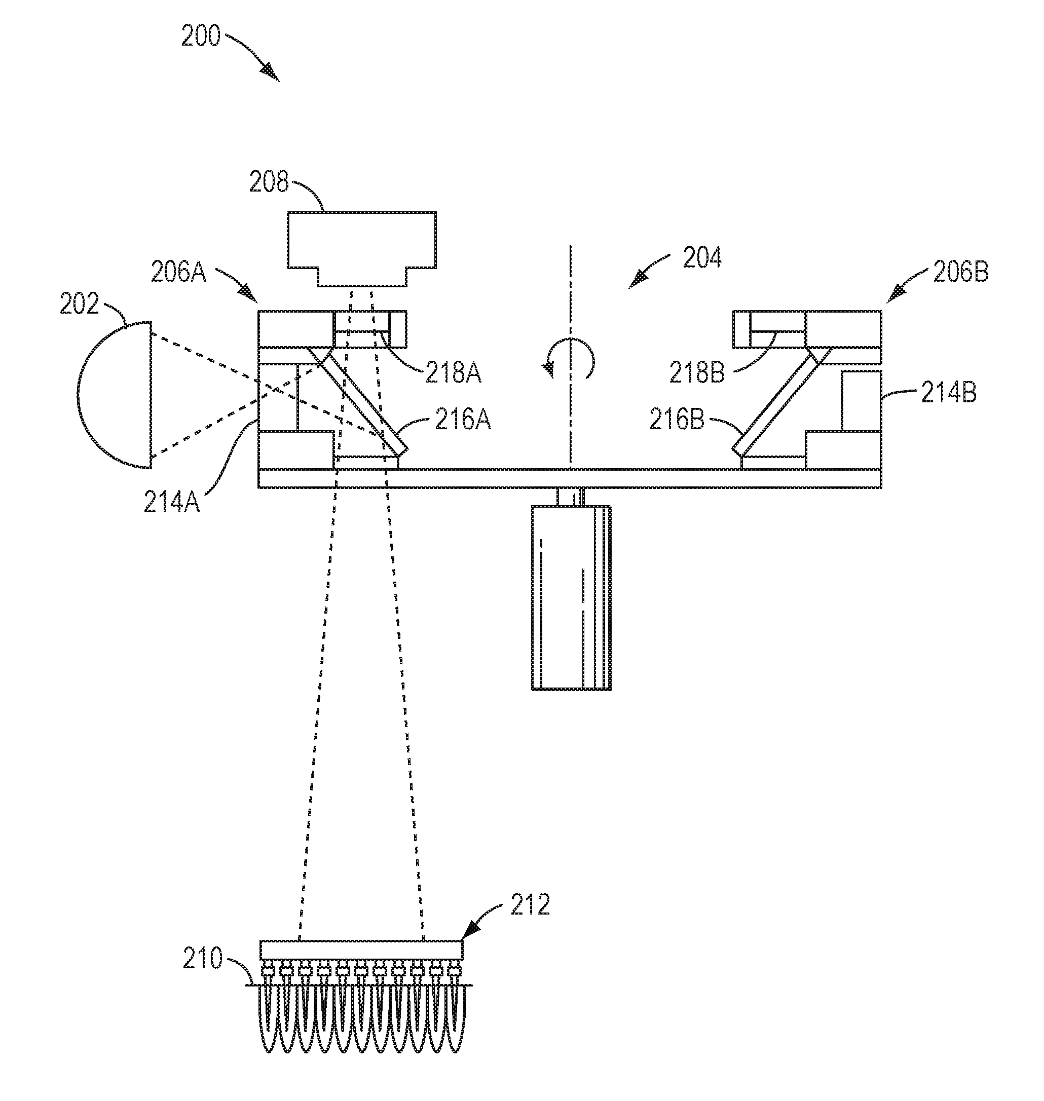
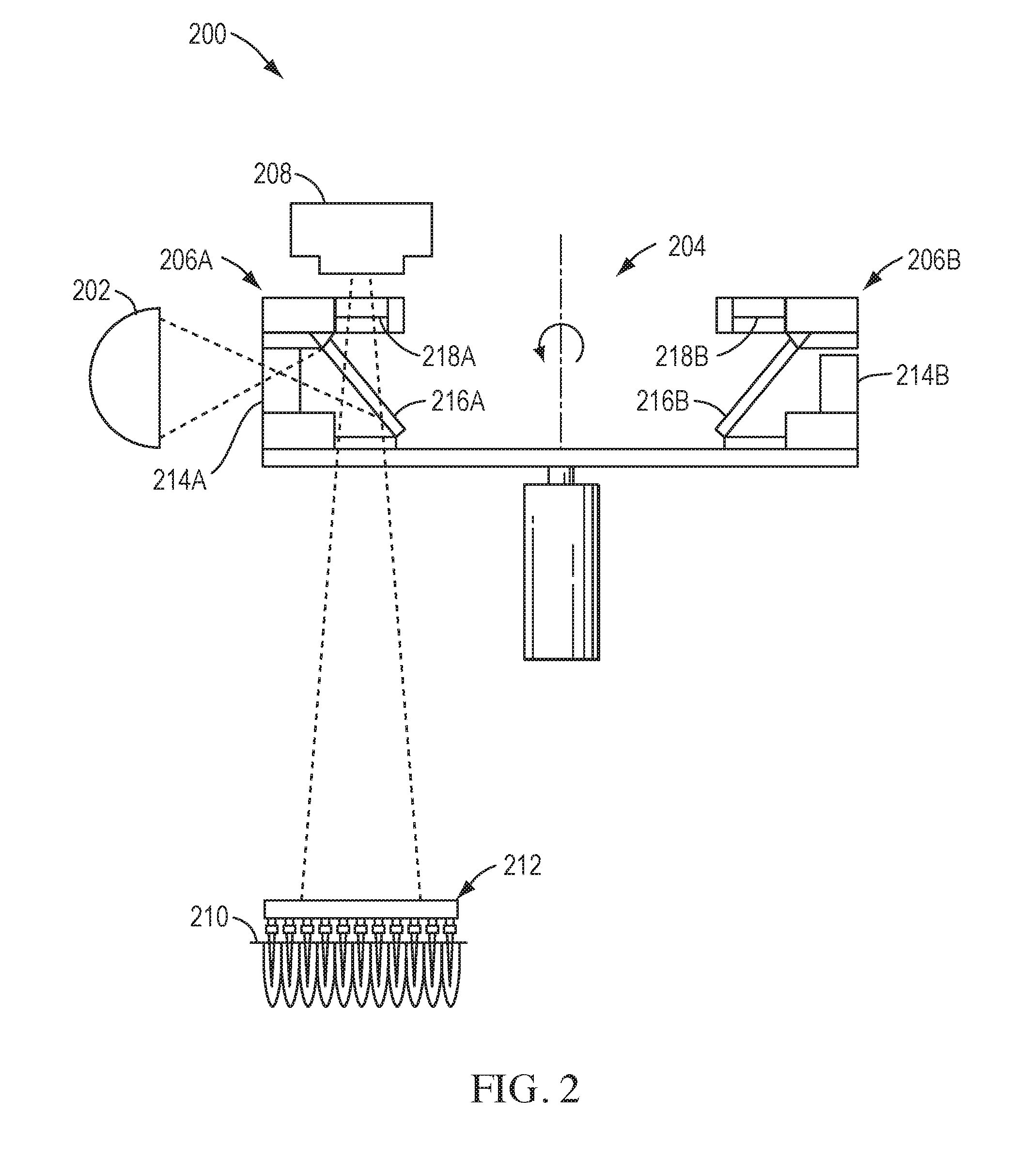
[0011]The present teachings relate to a method and system for determining a Region of Interest (ROI) for one or more biological samples in a laboratory instrument. In an embodiment of the present invention, the method comprises an optical system capable of imaging florescence emission from a plurality of sample wells. An initial ROI, its center location and size can be estimated from the fluorescence detected from each well. From this information

Problems solved by technology

Installation and calibration of laboratory instrumentation can be a time consuming and expensive process.
Man

Method used


Image

  • Methods and systems for determining optical regions of interest
  • Methods and systems for determining optical regions of interest
  • Methods and systems for determining optical regions of interest

Examples


Example

[0026]The following description of various embodiments is merely exemplary in nature and is in no way intended to limit the present teachings, applications or uses. Although the present teachings will be discussed in some embodiments as relating to polynucleotide amplification, such as polymerase chain reaction (PCR), such discussion should not be regarded as limiting the present teaching to only those applications.

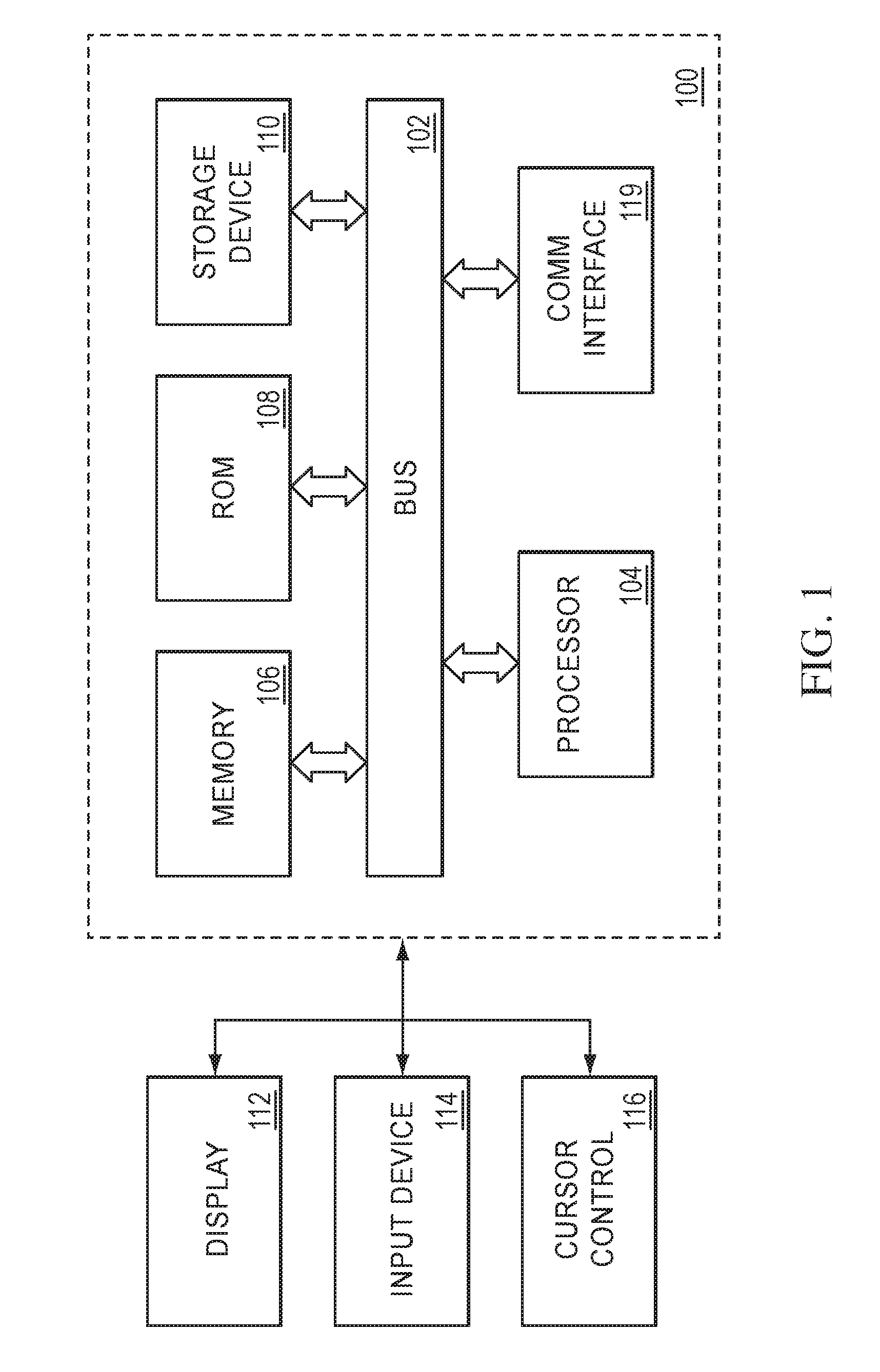
[0027]FIG. 1 is a block diagram that illustrates a computer system 100 upon which embodiments of the present teachings may be implemented. Computer system 100 includes a bus 102 or other communication mechanism for communicating information, and a processor 104 coupled with bus 102 for processing information. Computer system 100 also includes a memory 106, which can be a random access memory (RAM), or other dynamic storage device, coupled to bus 102, and instructions to be executed by processor 104. Memory 106 also may be used for storing temporary variables or other inte...


PUM


Abstract

The present teachings relate to a method and system for determining Regions of Interest (ROI) for one or more biological samples in a laboratory instrument. The method can include an optical system capable of imaging florescence emission from a plurality of sample wells. An initial ROI, its center location and size can be estimated from the fluorescence detected from each well. From this information the average size of the ROIs can be determined and global gridding models can be derived to better locate each of the ROIs. The global gridding models can then be applied to the ROIs to improve the precision of the ROI center locations. Sample wells not originally providing fluorescence ROIs can be recovered through the use of mapping functions. The radius of each ROI can then be adjusted to improve the signal-to-noise ratio of the optical system.

Description

CROSS-REFERENCE TO RELATED APPLICATIONS[0001]This application claims the benefit of priority of U.S. provisional application Ser. No. 62 / 113,058, filed Feb. 6, 2015, which is incorporated herein by reference in its entirety.BACKGROUND[0002]Installation and calibration of laboratory instrumentation can be a time consuming and expensive process. In many cases, engineers from the instrument supplier must be on site to perform these processes. This cost is generally passed on to the user. In some cases, experienced users can successfully calibrate properly manufactured instruments using multi-step procedures. During such calibrations, physical standards and well plates may be used in combination with manual procedures. Manual calibration processing and data inspection is error prone and may rely on ad hoc or subjective measures. While a final system verification step may provide resilience against accepting suboptimal calibrations, automation offers improved objectivity and uniformity d...

Claims


Application Information

Patent Timeline
IPC IPC(8): G01N21/76G06K9/00G01N21/77G06K9/32G06V10/25
CPCG01N21/763G01N21/77G01N2021/7786G01N2201/127G06K9/00134G06K9/3233G06T2207/30072G01N21/6428G01N21/6452G01N21/6456G06F19/18G06T2207/10064G06T2207/20216G01N21/274G06V20/695G06V10/25G01N21/84G06V20/693
Inventor CHU, YONG
Owner LIFE TECH CORP
Learn More