
Compressive imaging systems and methods

a compression imaging and imaging system technology, applied in the field of compression imaging systems, can solve the problems of limiting the potential operating rate of cutting-edge ultrahigh-speed imaging systems, limiting the speed, resolution, image quality of approaches,

Active Publication Date: 2016-08-11
THE JOHN HOPKINS UNIV SCHOOL OF MEDICINE
View PDF5 Cites 27 Cited by
  • Summary
  • Abstract
  • Description
  • Claims
  • Application Information

AI Technical Summary

Benefits of technology

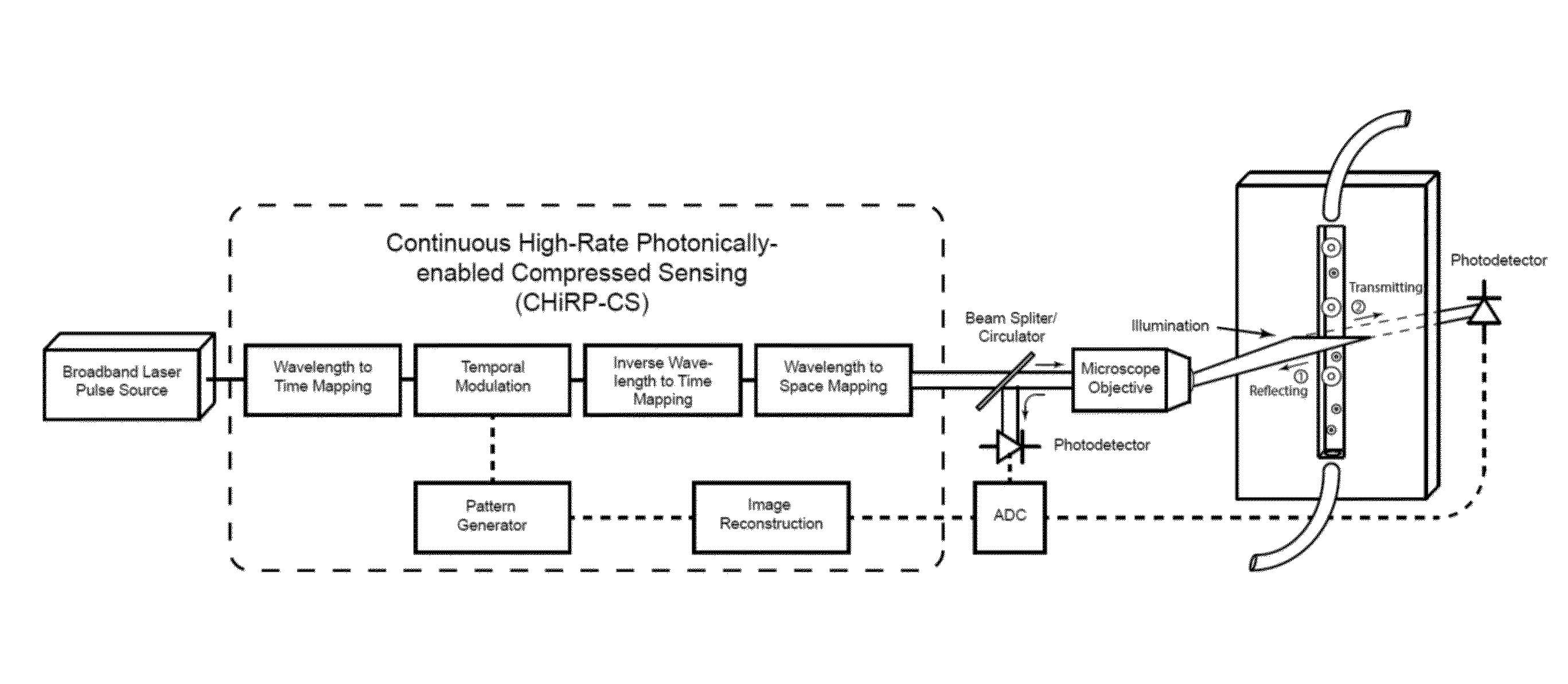
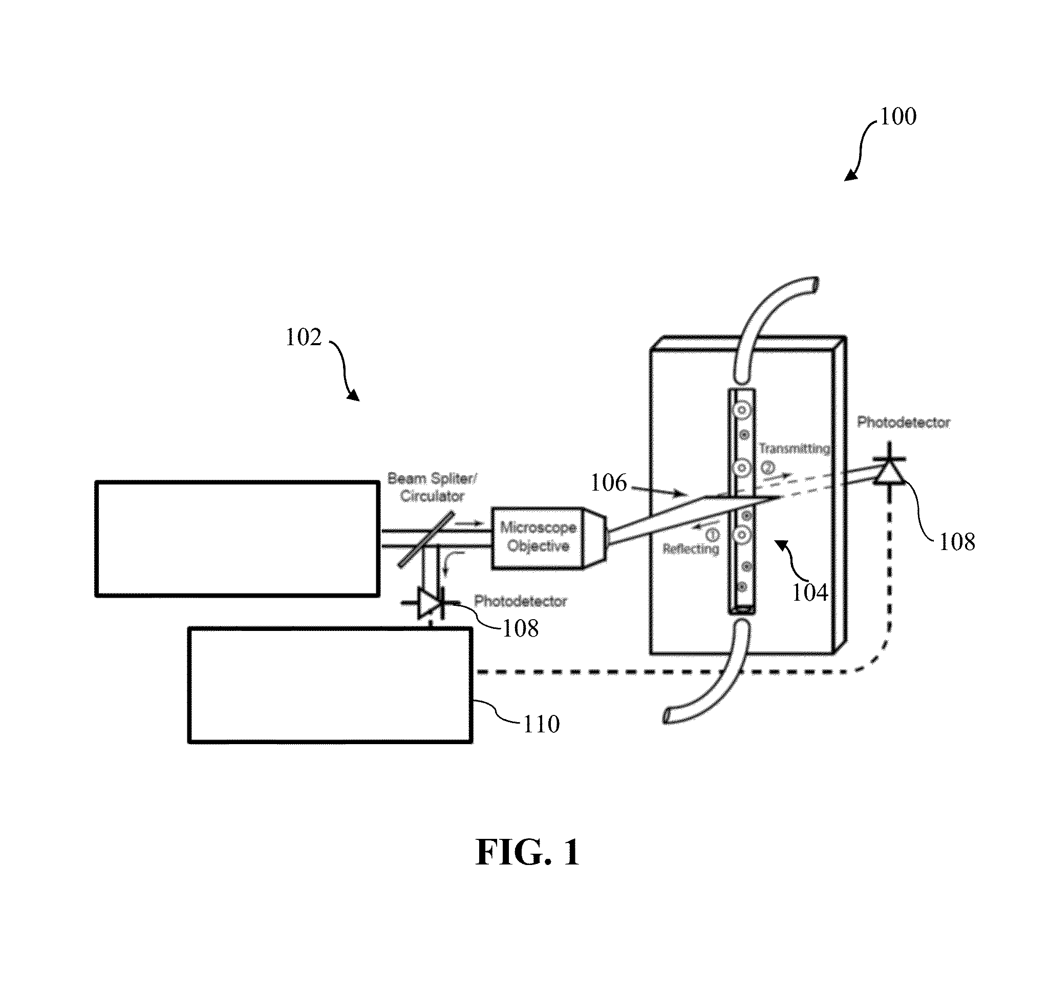
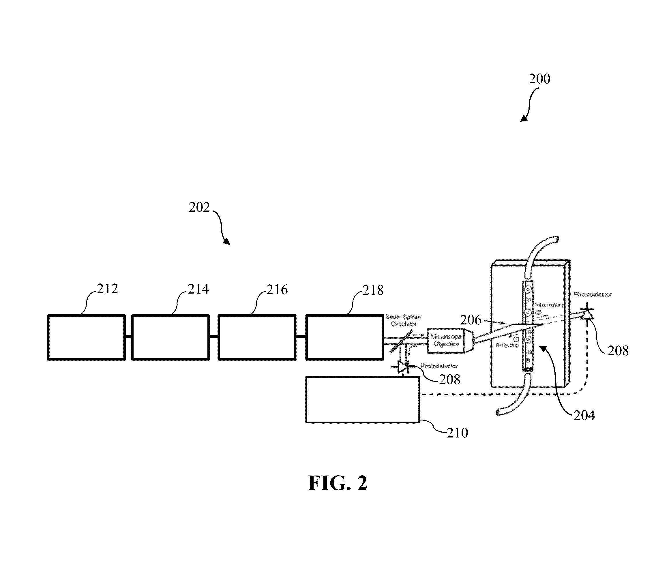
The patent describes a compressive imaging system and method that uses a plurality of light pulses with distinguishable spectra to create an image of an object of interest. The system includes an illumination system, a detection system, and an image processing system. The illumination system generates a plurality of light pulses with unique generalized spectra, while the detection system detects the pulses after being reflected, scattered, or transmitted through the object. The image processing system then creates an image of the object using information from the unique spectra of the pulses. The technical effects of this system and method include improved image quality, faster imaging, and improved depth of field.

Problems solved by technology

However, such approaches remain fundamentally limited in speed, resolution, and image quality by the measurement rate of electronic digitizers.
Thus cutting-edge ultrahigh-speed imaging systems are inefficient, collecting far more data than is required to accurately characterize the signals of interest and thus limiting their potential operating rate.

Method used


Image

  • Compressive imaging systems and methods
  • Compressive imaging systems and methods
  • Compressive imaging systems and methods

Examples


example 1

[0092][1] Petty, H. R., “Spatiotemporal chemical dynamics in living cells: from information trafficking to cell physiology,” Biosystems 83(23), 217-224 (2006).

[0093][2] Lang, P., Yeow, K., Nichols, A., and Scheer, A., “Cellular imaging in drug discovery,” Nat. Rev. Drug Discov. 5(4), 343-356 (2006).

[0094][3] Brouzes, E., Medkova, M., Savenelli, N., Marran, D., Twardowski, M., Hutchison, J. B., Rothberg, J. M., Link, D. R., Perrimon, N., and Samuels, M. L., “Droplet microfluidic technology for single-cell high-throughput screening,” Proc. Natl. Acad. Sci. U.S.A. 106(34), 14195-14200 (2009).

[0095][4] Rimon, N. and Schuldiner, M., “Getting the whole picture: combining throughput with content in microscopy,” J. Cell Sci. 124(22), 3743-3751 (2011).

[0096][5] Weaver, W. M., Tseng, P., Kunze, A., Masaeli, M., Chung, A. J., Dudani, J. S., Kittur, H., Kulkarni, R. P., and Carlo, D. D., “Advances in high-throughput single-cell microtechnologies,” Curr. Opin. Biotechnol. 25(0), 114-123 (2014).

[...

example 2

[0166][1] H. R. Petty, “Spatiotemporal chemical dynamics in living cells: from information trafficking to cell physiology,” Biosystems 83, 217-224 (2006).

[0167][2] P. Lang, K. Yeow, A. Nichols, and A. Scheer, “Cellular imaging in drug discovery,” Nat. Rev. Drug Discov. 5, 343-356 (2006).

[0168][3] E. Brouzes, M. Medkova, N. Savenelli, D. Marran, M. Twardowski, J. B. Hutchison, J. M. Rothberg, D. R. Link, N. Perrimon, and M. L. Samuels, “Droplet microfluidic technology for single-cell high-throughput screening,” Proc. Natl. Acad. Sci. U.S.A. 106, 14195-14200 (2009).

[0169][4] K. Goda, A. Ayazi, D. R. Gossett, J. Sadasivam, C. K. Lonappan, E. Sollier, A. M. Fard, S. C. Hur, J. Adam, C. Murray, C. Wang, N. Brackbill, D. Di Carlo, and B. Jalali, “High-throughput single-microparticle imaging flow analyzer,” Proc. Natl. Acad. Sci. U.S.A. (2012).

[0170][5] N. Rimon and M. Schuldiner, “Getting the whole picture: combining throughput with content in microscopy,” J. Cell Sci. 124, 3743-3751 (201...

example 3

[0221][1] K. Goda, K. K. Tsia, and B. Jalali, “Serial time-encoded amplified imaging for real-time observation of fast dynamic phenomena.” Nature 458, 1145 (2009).

[0222][2] M. A. Davenport, M. F. Duarte, Y. C. Eldar, and G. Kutyniok, “Introduction to compressed sensing,” in “Com-pressed Sensing: Theory and Applications,”, Y. C. Eldar and G. Kutyniok, eds. (Cambridge University Press, 2012), pp. 1-68.

[0223][3] M. Duarte, M. Davenport, D. Takhar, J. Laska, T. Sun, K. Kelly, and R. Baraniuk, “Single-pixel imaging via compressive sampling,” Signal Processing Magazine, IEEE 25, 83-91 (2008).

[0224][4] G. C. Valley, G. A. Sefler, and T. J. Shaw, “Compressive sensing of sparse radio frequency signals using optical mixing,” Opt. Lett. 37, 4675-4677 (2012).

[0225][5] B. T. Bosworth and M. A. Foster, “High-speed ultrawideband photonically enabled compressed sensing of sparse radio frequency signals,” Opt. Lett. 38, 4892-4895 (2013).

[0226][6] E. J. Candès, J. K. Romberg, and T. Tao, “Stable sign...


PUM


Abstract

A compressive imaging system includes an illumination system arranged to illuminate an object of interest with illumination light, and a detection system configured to detect at least a portion of the illumination light after being at least one of reflected from, scattered from, or transmitted through the object of interest or to detect fluorescent light from the object of interest and to provide an imaging signal. The compressive imaging system further includes an image processing system configured to communicate with the detection system to receive the imaging signal. The illumination light from the illumination system comprises a plurality of light pulses such that each light pulse has a preselected spectrum that is distinguishable from spectra of all other pulses. The image processing system is configured to form an image of the object of interest using information concerning the preselected spectra of the plurality of light pulses.

Description

CROSS-REFERENCE OF RELATED APPLICATION[0001]This application claims priority to U.S. Provisional Application No. 62 / 113,215 filed Feb. 6, 2015, the entire content of which is hereby incorporated by reference.[0002]This invention was made with U.S. Government support under grant number ECCS-1254610 awarded by the National Science Foundation (NSF). The U.S. Government has certain rights in the invention.BACKGROUND[0003]1. Technical Field[0004]The field of the currently claimed embodiments of this invention relates to imaging systems, and more particularly to compressive imaging systems.[0005]2. Discussion of Related Art[0006]Ultrahigh-speed continuous imaging is a key enabling technology for investigations throughout the life and physical sciences. Though burst imaging systems such as CMOS and CCD imaging arrays with in situ storage are useful for observing isolated events, many applications (e.g. high-throughput diagnostics) necessitate continuous imagers, which require considerable ...

Claims


Application Information

Patent Timeline
Patent Type & Authority Applications(United States)
IPC IPC(8): G02B21/00
CPCG02B21/008G02B21/0064G02B21/0076G02B21/0032
Inventor BOSWORTH, BRYAN T.FOSTER, MARK A.STROUD, JASPER R.TRAN, TRACCHIN, SANGTRAN, DUNG
Owner THE JOHN HOPKINS UNIV SCHOOL OF MEDICINE
Learn More