Microphone Module With Shared Middle Sound Inlet Arrangement

Active Publication Date: 2016-08-11
SONION NEDERLAND
View PDF10 Cites 2 Cited by
  • Summary
  • Abstract
  • Description
  • Claims
  • Application Information

AI Technical Summary

Problems solved by technology

It is a disadvantage of the matched pair that in case of a mismatch/drift the directivity degrades heavily, in particular in the low frequency ranges.
Moreover, matching microphones as well as amplitude/phase correction in the hearing aid production are time consuming manual operations.
However, the notch angle is at a fixed position and cann

Method used


Image

  • Microphone Module With Shared Middle Sound Inlet Arrangement
  • Microphone Module With Shared Middle Sound Inlet Arrangement
  • Microphone Module With Shared Middle Sound Inlet Arrangement

Examples


embodiment 300

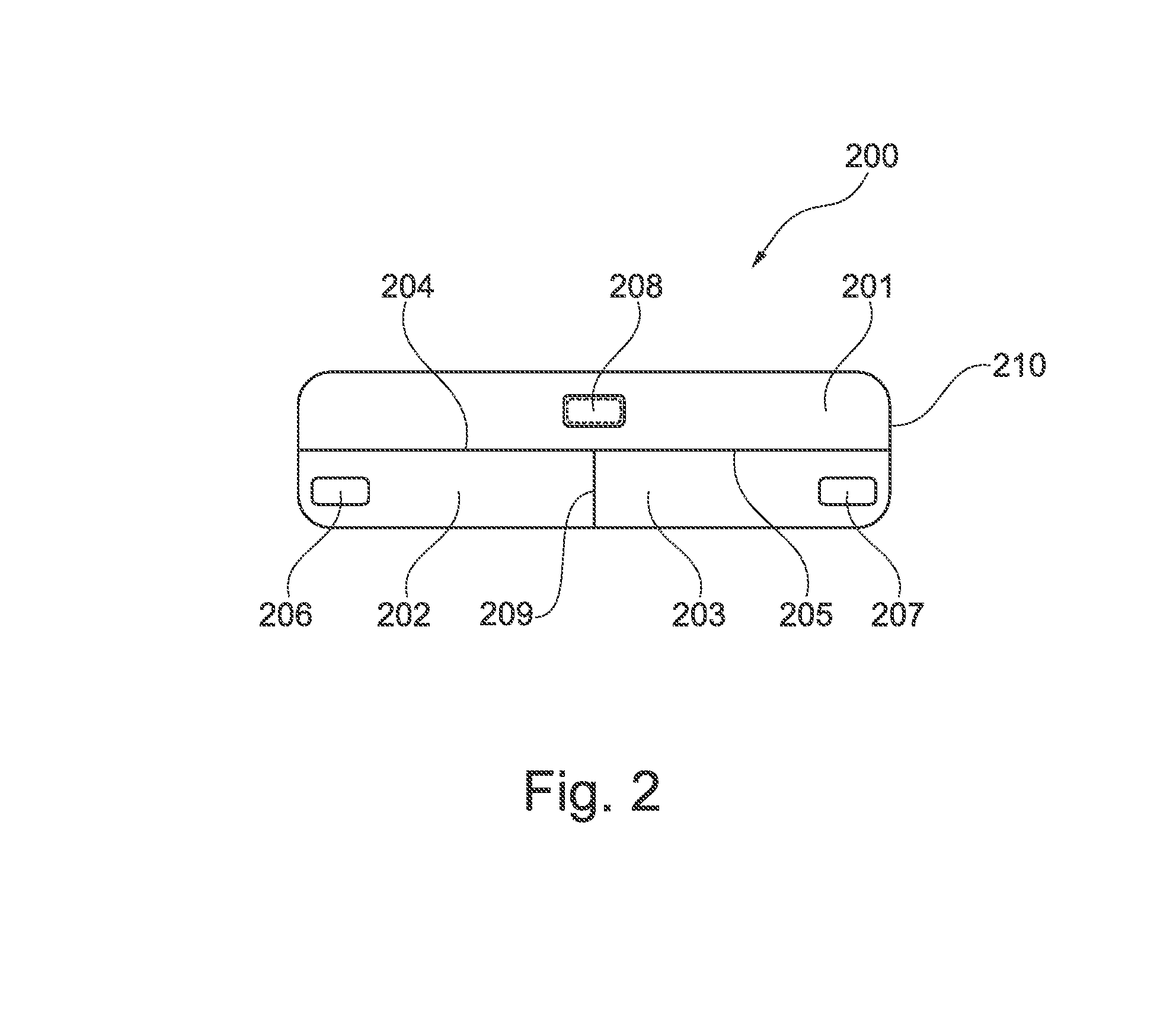
[0041]In the embodiment 300 depicted in FIG. 3 the middle volume of FIG. 2 has been separated into middle volumes 301 and 302. The front 303 and rear 304 volumes are still separated and they are still in acoustical communication with sound inlets 307 and 308, respectively. The middle volume 301, the front volume 303 and the membrane 305 form a directional microphone having for instance a cardioid polar pattern. Similarly, the middle volume 302, the rear volume 304 and the membrane 306 form another directional microphone having for instance an anti-cardioid polar pattern. The shared sound inlet 309, 310 is in acoustical connection with middle volumes 301 and 302, respectively. An acoustical resistance is arranged in sound inlet 309, 310. As addressed in relation to FIG. 2 the acoustical resistance may be formed by a grid. Again, the two directional microphones share the same outer housing or cabinet 311.

embodiment 400

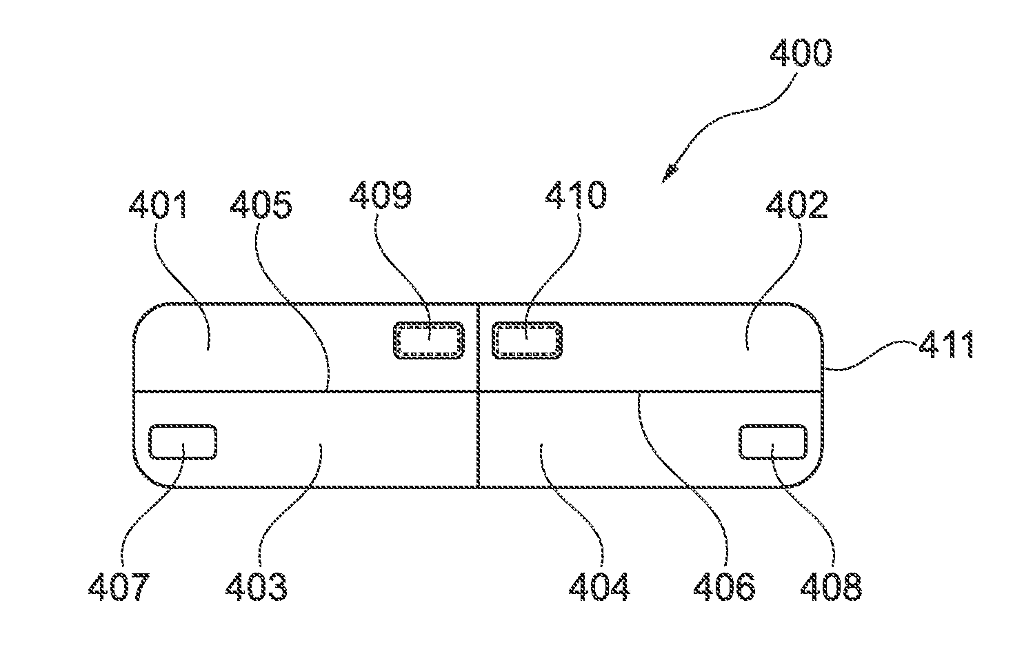
[0042]Referring now to the embodiment 400 shown in FIG. 4 the shared sound inlet of FIG. 3 has been separated into individual sound inlets 409 and 410 each holding an acoustical resistance. Otherwise the embodiment shown in FIG. 4 is identical to the embodiment shown in FIG. 3 with separated middle volumes 401 and 402, and separated front 403 and rear 404 volumes. The cardioid response is provided by membrane 405, whereas membrane 406 generates the anti-cardioid response. Cardioid and anti-cardioid responses are only used as examples. Membrane 405 and 406 may in principle generate any back-to-back polar patterns. The front 403 and rear 404 volumes are in acoustical communication with sound inlets 407 and 408, respectively. Similar to FIGS. 2 and 3 the two microphones share the same outer housing or cabinet 411.

embodiment 500

[0043]FIG. 5 shows an embodiment 500 being almost identical to the embodiment shown in FIG. 4. Again separated middle volumes 501 and 504 and separated front 503 and rear 502 volumes are applied. The cardioid response is provided by membrane 505, whereas membrane 506 generates the anti-cardioid response. Again, cardioid and anti-cardioid responses are only used as examples. Membrane 505 and 506 may in principle generate any back-to-back polar patterns. An acoustical resistance is provided in sound inlets 509 and 510, whereas sound inlets 507 and 508 are without any acoustical delays. Similar to FIG. 4 the two microphones share the same outer housing or cabinet 511.


PUM


Abstract

The present invention relates to a microphone module comprising a first directional microphone comprising a front sound inlet and a front membrane, a second directional microphone comprising a rear sound inlet and a rear membrane, and a middle sound inlet arrangement being acoustically connected to the front and rear membranes, said middle sound inlet arrangement comprising acoustical resistance means arranged at least partly therein. The microphone module aims at generating a cardioid and an anti-cardioid response, or alternatively any other back-to-back polar patterns.

Description

FIELD OF THE INVENTION[0001]The present invention relates to a microphone module comprising first and second directional microphones having back-to-back polar patterns. In particular, the present invention relates to a microphone module comprising a first directional microphone having a cardioid polar pattern, and a second directional microphone having an anti-cardioid polar pattern. Moreover, the present invention relates to a hearing aid comprising such a microphone module.BACKGROUND OF THE INVENTION[0002]Various techniques to achieve directional hearing in a hearing aid have been suggested over the years. Examples of such techniques are as follows:[0003]Matched pair of two omni-directional microphones: Directional hearing in hearing aids may be achieved by the use of a matched pair of two omni-directional microphones. To generate a directional output signal the signals from the omni-directional microphones are subtracted. An electrical time delay may be applied to one of the sign...

Claims


Application Information

Patent Timeline
IPC IPC(8): H04R1/28H04R25/00H04R1/32
CPCH04R1/2884H04R2201/003H04R25/405H04R1/326
Inventor SÄNGER, ANNE-MARIEWASYLKÓW, ARKADIUSZ
Owner SONION NEDERLAND
Why Eureka
Try Eureka