Sealing assembly for rolling bearings, in particular for a hub bearing unit of vehicles and associated hub bearing unit

a technology for sealing assembly and rolling bearing, which is applied in the direction of mechanical equipment, rotary machine parts, transportation and packaging, etc., can solve the problems of reducing the sealing efficiency, affecting the sealing effect, so as to achieve excellent hydraulic sealing characteristics, reduce friction, and reduce the effect of overall dimensions

Active Publication Date: 2016-08-18
AB SKF
View PDF4 Cites 21 Cited by
  • Summary
  • Abstract
  • Description
  • Claims
  • Application Information

AI Technical Summary

Benefits of technology

[0005]The object of the present invention is to provide a sealing assembly for rolling bearings, particularly but not exclusively suitable to be used in a hub bearing unit of a vehicle wheel, having excellent hydraulic sealing characteristics against external contaminants, low overall dimensions and low friction.

Problems solved by technology

The known seal assemblies are relatively satisfactory, but often have large overall dimensions and relatively high friction.
This, however, may decrease the efficiency of the seal, allowing a small part of the contaminants to come in contact with the one sliding lip, resulting in a premature wear of the same.
In addition, both due to machining tolerances and the so-called “cornering” stresses in use, sliding seals, especially axial ones may possibly perform incorrectly.
Actually, the contaminants that penetrate beyond the labyrinth seal are then discharged only with difficulty from a collecting chamber internal to the seal and thus increase the wear of the contacting lip.
Furthermore the “cornering” problem is not solved.

Method used


Image

  • Sealing assembly for rolling bearings, in particular for a hub bearing unit of vehicles and associated hub bearing unit
  • Sealing assembly for rolling bearings, in particular for a hub bearing unit of vehicles and associated hub bearing unit
  • Sealing assembly for rolling bearings, in particular for a hub bearing unit of vehicles and associated hub bearing unit

Examples


Embodiment Construction

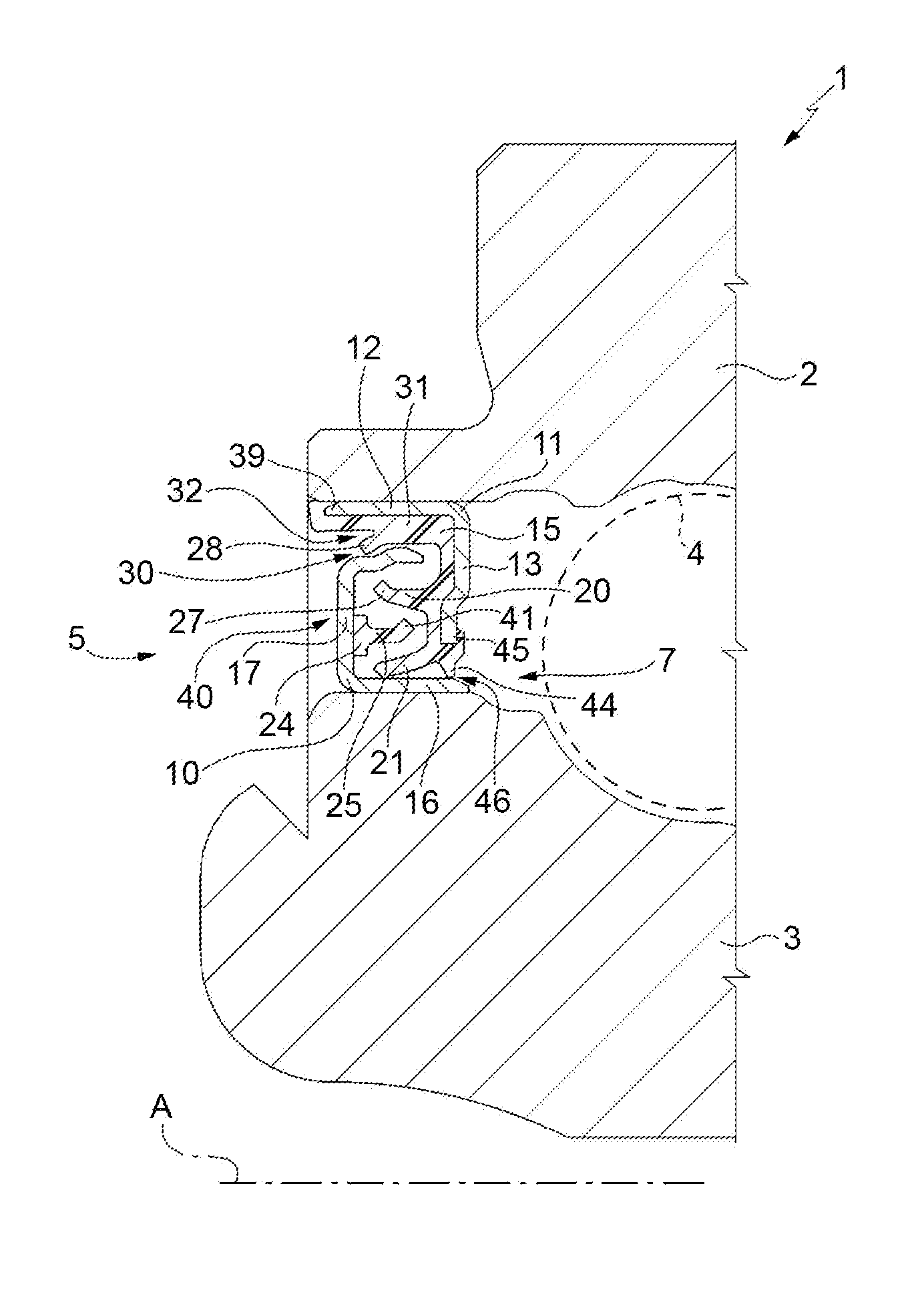
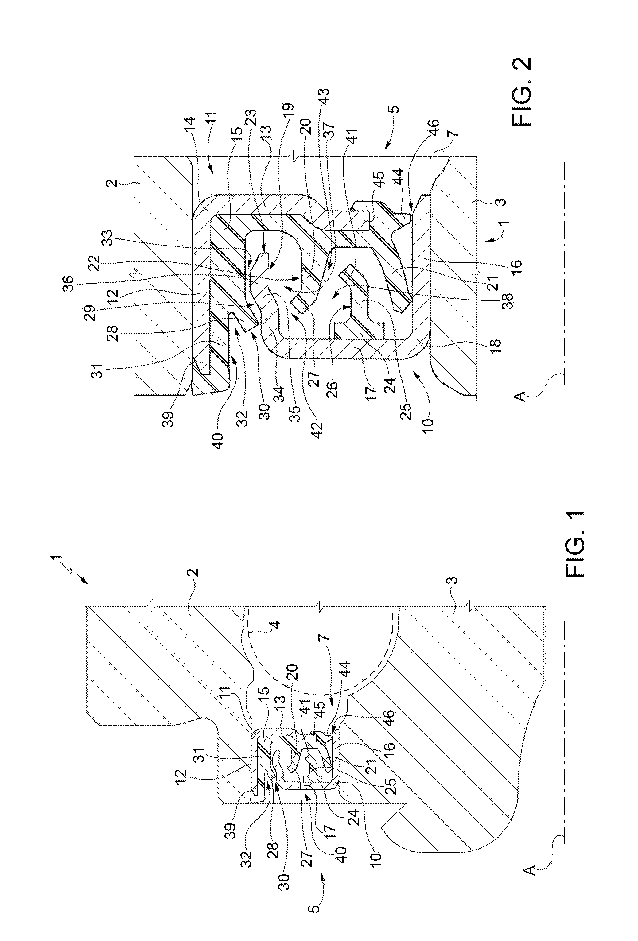
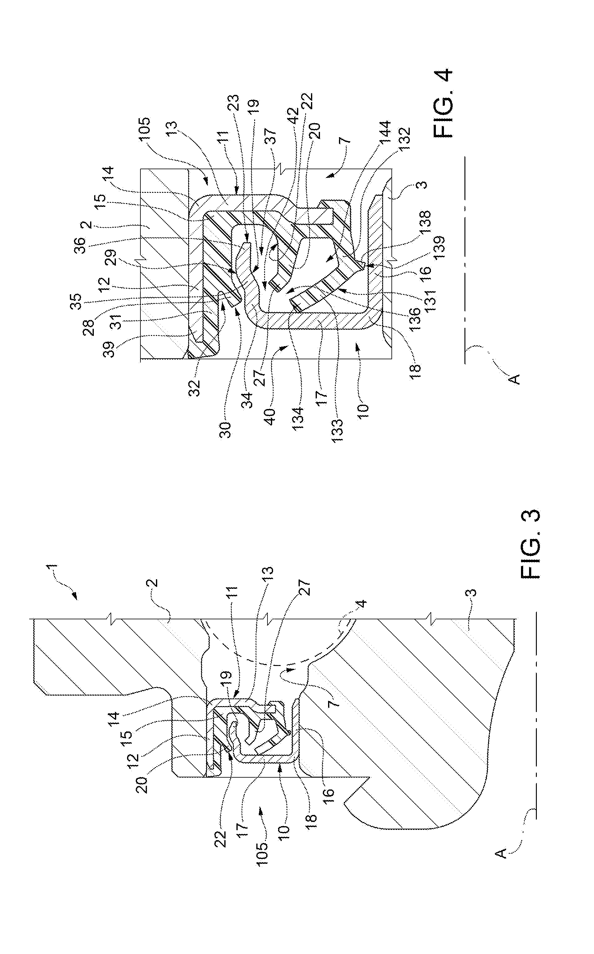
[0013]With reference to FIG. 1, reference number 1 denotes as a whole a rolling bearing, in the example illustrated constituting a hub bearing unit and comprising an outer ring 2, an inner ring 3, a plurality of rolling bodies 4 (only one of which for sake of clarity is shown in dashed-lines) interposed between the outer ring 2 and the inner ring 3 to make them rotatable, one with respect to the other, about a common rotation axis A, and a seal assembly 5, arranged fitted in-between the rings 2 and 3, illustrated truncated for simplicity, to close an annular space 7 radially bounded between the rings 2 and 3 and which accommodates the rolling bodies 4.

[0014]Generally, the rings 2 and 3 may be part of a rolling bearing of any known type, whether it is part or not of the hub bearing unit 1. In any case, the outer ring 2 is stationary in use, while the inner ring 3 is rotating in use around a relative common rotation axis A of the rings 2 and 3, which in general is also a common symmet...


PUM


Abstract

A sealing assembly insertable between a stationary outer ring and a rotating inner ring of a bearing or hub bearing unit, having a first C-shaped shield supported by the inner ring and a second L-shaped shield supported by the outer ring. The first shield has a first annular sealing element having a first annular lip that extends axially cantilevered from the flange portion of the second shield in a position facing a radially outer sleeve shaped portion of the first shield and a second annular lip, elastically deformable, arranged radially on the inside of the first lip and which cooperates in contact with a radially inner sleeve shaped portion of the first shield, which carries a second sealing element having a third annular lip, which extends axially cantilevered from the first shield and towards the second shield and which is radially interposed between the first and the second lip.

Description

TECHNICAL FIELD OF THE INVENTION[0001]The present invention relates to a sealing assembly for rolling bearings, in particular for use in a hub bearing unit of vehicles, particularly, but not exclusively, useful both on the “outboard” side, i.e. facing, in use, the vehicle external body side of the unit itself, and “inboard”, i.e. facing the inside of the vehicle, having high sealing efficiency against external contaminants and low friction, as well as to a hub bearing unit provided with the same.KNOWN ART[0002]As known, the hub bearing units of vehicles comprise an outer ring, for example stationary in use, and an inner ring, for example rotating in use, provided on the outboard side of the hub bearing unit with a mounting flange for a vehicle wheel. Between the inner and outer rings respective seal assemblies are interposed, one on the outboard side and one on the opposite side, referred to as “inboard”.[0003]Among the most used seal assemblies, not only on hub bearing units but mo...

Claims


Application Information

Patent Timeline
Patent Type & Authority Applications(United States)
IPC IPC(8): B60B27/00F16C33/78F16J15/3232F16C33/80F16J15/00F16J15/447
CPCB60B27/0073F16J15/002F16J15/447B60B2900/511F16C33/805F16C33/782F16C33/7896F16J15/3232B60B27/0005F16C33/7806F16C33/7816F16C33/7823F16C33/7826F16C33/7889F16C2326/02F16J15/3264F16C33/7883F16C19/184F16C33/80F16C2240/60
Inventor GULLCARMELOOLIVIERI, DAVIDE ANTONIOORGANISCIAK, MICHELPANCHETTI, MARCOVILLALOBOS, HECTOR
Owner AB SKF
Why Eureka
Try Eureka