Coil spring modeling apparatus and method of the same

a technology of coil springs and models, applied in the direction of process and machine control, instruments, educational appliances, etc., can solve the problems of affecting the steering performance of vehicles, and affecting the performance of steering, etc., and achieve the effect of measuring accurately

Active Publication Date: 2016-08-18
NHK SPRING CO LTD
View PDF3 Cites 4 Cited by
  • Summary
  • Abstract
  • Description
  • Claims
  • Application Information

AI Technical Summary

Benefits of technology

[0010]Accordingly, an object of the present invention is to provide a coil spring modeling apparatus which enables a kingpin moment (KPM) to be measured accurately, and a method of controlling the same.

Problems solved by technology

However, producing a variety of coil springs whose force line positions are different by way of trial is time consuming and costly.
The kingpin moment (KPM) becomes a factor which adversely affects the steering performance of a vehicle.
However, in reality, since the bearing has friction, rotation of the upper spring seat meets resistance.
Consequently, the actuator unit is twisted and the force line position (FLP) is also changed, which causes a problem that the kingpin moment (KPM) cannot be measured accurately.

Method used


Image

  • Coil spring modeling apparatus and method of the same
  • Coil spring modeling apparatus and method of the same
  • Coil spring modeling apparatus and method of the same

Examples


Embodiment Construction

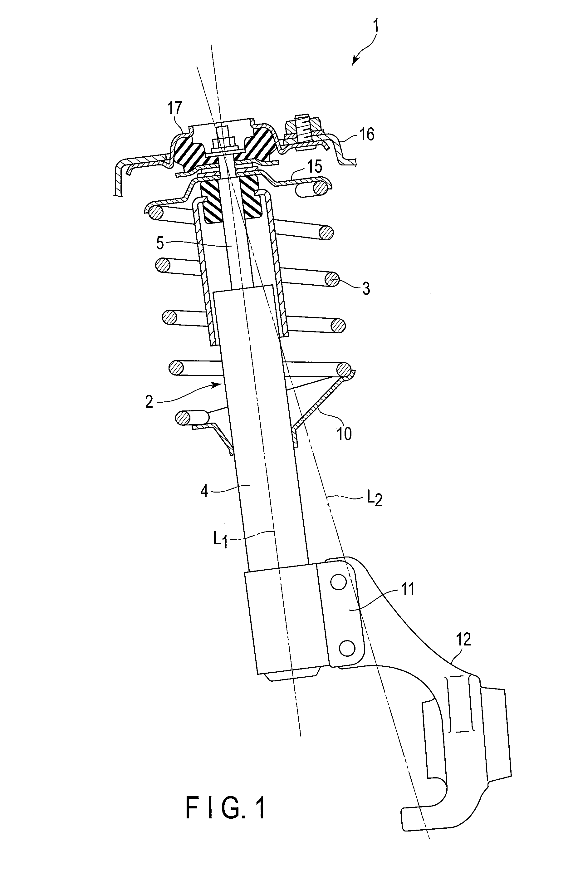
[0027]FIG. 1 shows a McPherson-strut-type suspension 1, which is an example of a suspension system used in vehicles. The suspension 1 comprises a shock absorber as a strut 2, and a suspension coil spring 3 (which is hereinafter simply referred to as a coil spring 3). The strut 2 comprises an outer tube 4 as a first strut element, and a rod 5 as a second strut element. The rod 5 is inserted into the outer tube 4. A damping force generation mechanism is provided at a distal end of the rod 5 inserted into the outer tube 4. The outer tube 4 and the rod 5 can be moved relatively along axis L1 (strut axis).

[0028]The outer tube 4 is provided with a lower spring seat 10. At the lower end of the outer tube 4, a bracket 11 is provided. A knuckle member 12 is mounted on the bracket 11. A wheel axis is supported by the knuckle member 12. An upper spring seat 15 is provided near the upper end of the rod 5. A mount insulator 17 is provided between the upper spring seat 15 and a body member 16. Wh...


PUM


Abstract

A coil spring modeling apparatus includes a first attachment member disposed on a lower spring seat, a second attachment member disposed on an upper spring seat, an actuator unit formed of a Stewart-platform-type parallel mechanism, a hydraulic pressure supply device, a torsion detection mechanism, and a controller. The torsion detection mechanism is constituted of displacement gauges such as a linear variable differential transformer. The displacement gauges are provided on hydraulic cylinders, and detect amounts of displacement relative to the reference lengths of the hydraulic cylinders, respectively. The controller calculates a relative torsional angle between the first attachment member and the second attachment member based on the detected displacement.

Description

BACKGROUND OF THE INVENTION[0001]1. Field of the Invention[0002]The present invention relates to a coil spring modeling apparatus capable of producing a reactive force (repulsive force) corresponding to compression of a helical spring such as a suspension coil spring, and a method of controlling the same.[0003]2. Description of the Related Art[0004]As an example of a vehicle suspension system, a McPherson-strut-type suspension is known. The McPherson-strut-type suspension comprises a coil spring, and a strut (a shock absorber) provided inside of the coil spring. The coil spring is compressed by a load applied from above the coil spring, and is extended and retracted in accordance with the load. The strut is also extended and retracted.[0005]In the McPherson-strut-type suspension, in order to reduce the sliding resistance of a strut, offsetting a force line position (FLP) of a coil spring from the center line of the coil spring is known. For example, the force line position (FLP) of ...

Claims


Application Information

Patent Timeline
Patent Type & Authority Applications(United States)
IPC IPC(8): F16F1/04G05B17/02
CPCF16F1/04F16F2230/0017G05B17/02G09B23/08G09B25/025G01L3/00
Inventor NAKAMURA, TAKAHIROFURUKAWA, KAZUOMORIYAMA, SENRISATO, RYUICHINISHIZAWA, SHINICHI
Owner NHK SPRING CO LTD
Why Eureka
Try Eureka