Fire rated recessed lighting assembly

a technology of recessed lighting and assembly, which is applied in the direction of fixed installation, lighting and heating equipment, lighting support devices, etc., can solve the problems of requiring a larger joist, requiring multiple subcontractors, and not being designed for standard 28 joist construction, etc., to slow down the spread of fir

Active Publication Date: 2016-08-18
ELITE LIGHTING
View PDF2 Cites 9 Cited by
  • Summary
  • Abstract
  • Description
  • Claims
  • Application Information

AI Technical Summary

Benefits of technology

[0005]Provided is a fire rated or resistant recessed lighting assembly comprising: a) a metal housing inside of which a light is placed, the metal housing having an open and a closed end; b) a trim (a decorative trim and / or an adapter); and c) an object (element) made of a fire resistant material, such as an intumescent material placed inside of the housing in between the closed end of the housing and the trim; wherein in event of a fire, the fire resistant material slows spread of fire. If the fire resistant material is an intumescent material, then the intumescent material expands to slow spread of the fire. The object (fire resistant element) can span the diameter of the housing just short of touching the housing. The trim can be a decorative trim that may or may not also act as a reflector. The trim can be a support trim (an adapter), which may have a tubular section that fits inside of the housing, and a flange that extends in annular relationship outside of the opening of the housing. The light assembly can further comprise wires attached to top of the housing, to which wires the intumescent object is slidably or movably attached, wherein in event of a fire, the decorative trim melts and the intumescent material slides or moves down the wires. The light assembly can further comprise stoppers attached to an end of the wires for stopping the intumescent object from further sliding down. The light assembly can further comprise a bracket for attaching the wires to the top of the housing. The intumescent object can be a disc made of an intumescent material. The intumescent disc can have a central opening. A socket in electronic communication with an electric cable from a junction box on outside of the housing can be placed inside of the housing, with a least a portion of the socket or the electric cable passing through the central opening of the disc inside of the housing. Heat vents can be present on the intumescent disc. An intumescent ring can be placed outside of the housing to cover one or more openings for attaching the housing to a structure outside of the housing. The disc can be slidably attached to the closed end of the housing with wires. One or more metal wires can be attached to the closed end of the housing, the intumescent disc slidably attached to the wires. A support can be attached to the open end of the housing. A cover can be used for covering the intumescent ring to sandwich the intumescent ring in between the cover and the housing. A metal support below the intumescent disc can be used, the metal disc having openings through which the wires pass to allow the metal support and the intumescent disc slide. One or more stoppers attached at a second end of the wire can be used to stop the metal support from falling out when the metal support reaches the second end of the wire. A metal frame for attaching the housing through a connection with the slot of the housing can be used. A cover can be used for covering the intumescent ring to sandwich the intumescent ring in between the cover and the housing.

Problems solved by technology

The problem with fire boxes is that multiple subcontractors may be needed to install a recessed light.
The fire boxes may not be designed for standard 2×8 joist construction, requiring larger joist that may be more expensive to construct.
Due to the size of the box, recessed lights cannot be installed in close proximity to each other or close to the wall.
The fire box can only be installed along a long axis.
Furthermore, requiring installing the fire box first and then installing the recessed light inside the box can cause delays in construction and increases the overall cost of labor and material.
Lastly, because a box must be made from drywall around each recessed light, additional clearance is needed, thereby limiting location.

Method used


Image

  • Fire rated recessed lighting assembly
  • Fire rated recessed lighting assembly
  • Fire rated recessed lighting assembly

Examples


Embodiment Construction

[0028]Provided is a fire rated recessed lighting assembly that can contain a fire for at least 60 or 120 hours without the need of a fire box around the recessed lighting assembly. The elimination of the fire box or other fire deterrent construction reduces the cost of installation and allows for the flexibility of arranging the lighting assembly in more locations and closer arrangements. The fire rated recessed lighting assembly is adapted to be disposed in relation to an opening defined in a surface of a structure (i.e. a hole or trough cut into a wall or suspended ceiling) such that a socket (with a lamp or LED strips) can be installed in the light assembly / fixture through the opening.

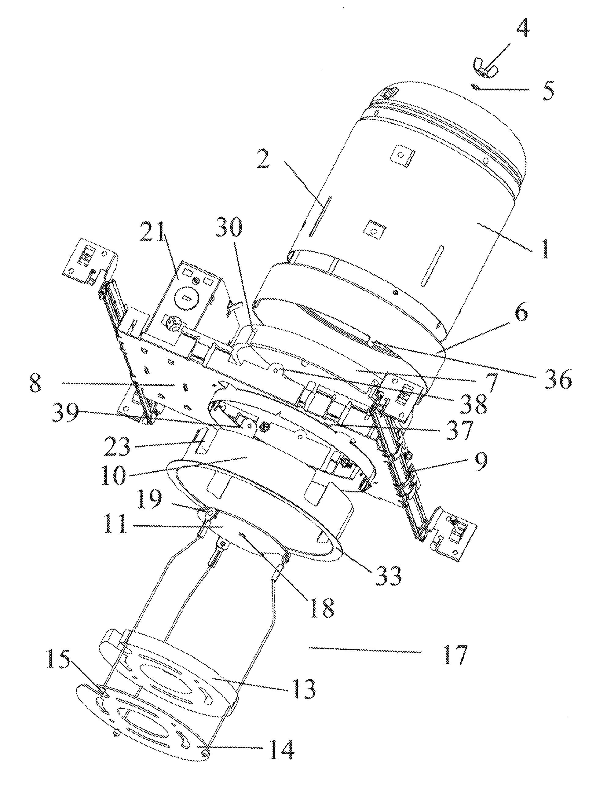
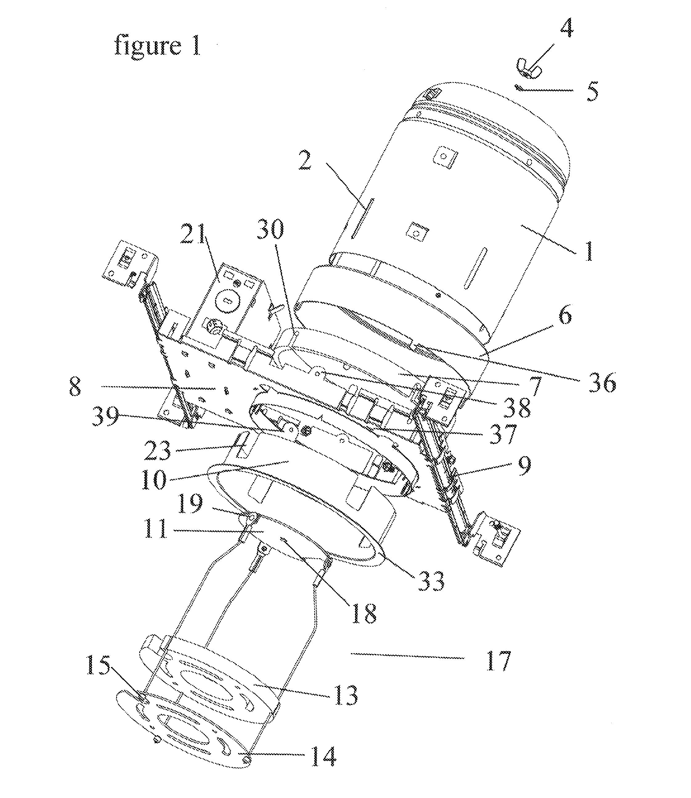
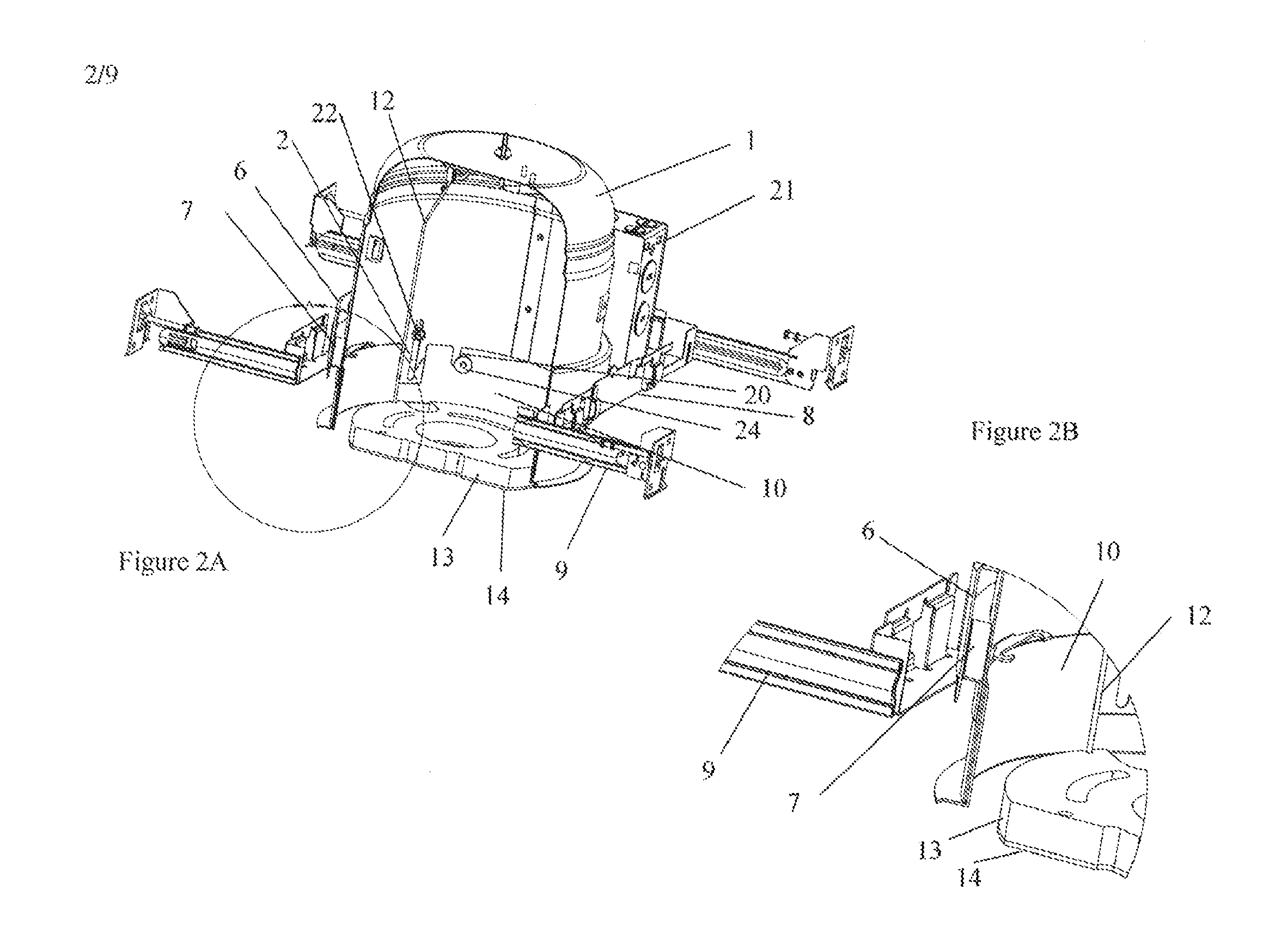
[0029]FIG. 1 is an exploded view of the fire rated recessed lighting assembly. The recessed lighting assembly has a housing 1. The housing can be in the shape of a can, with a tubular body with an open end and a closed end. The open end at the bottom of the can is an aperture that generally faces do...


PUM


Abstract

Provided is a fire rated or resistant recessed lighting assembly including a metal housing inside of which a lighting unit is placed, the housing being fire resistant for 120 minutes when tested according ASTM E119-12a without a protective fire resistant cover on outside of the housing. The fire resistant recessed lighting assembly can include a metal housing inside of which a light is placed and one or both of: i) an object made of a fire resistant material, such as an intumescent material, placed inside of the housing in between a trim and a closed end of the housing; and ii) an ring made of a fire resistant material, such as an intumescent material, placed outside of the housing, wherein in event of a fire, the intumescent material expands to slow spread of the fire.

Description

CROSS-REFERENCE[0001]The present application is a continuation-in-part (CIP) of U.S. patent application Ser. No. 14 / 677,979 filed on Apr. 3, 2015, which claims the benefit of provisional application No. 62 / 116,871, filed on Feb. 16, 2015, and also claims benefit of provisional application No. 62 / 239,180, filed on Oct. 8, 2015, which are all incorporated herein by reference in their entirety.BACKGROUND SECTION OF THE INVENTION[0002]Recessed luminaries are placed in the ceiling and there is a need that they contain a fire for between 60 to 120 minutes, otherwise a fire from one lighting assembly in a ceiling can spread to a floor above the ceiling where the lighting assembly is placed.[0003]To address the issue of fire rated lighting assembly, generally an enclosure is built around a recessed light. These enclosures include a fire box that surrounds the recessed light. The problem with fire boxes is that multiple subcontractors may be needed to install a recessed light. The fire boxes...

Claims


Application Information

Patent Timeline
Patent Type & Authority Applications(United States)
IPC IPC(8): F21V25/12F21S8/02F21V23/06
CPCF21V25/125F21S8/026F21V23/06F21S8/02F21V21/047F21V23/002F21Y2115/10
Inventor RASHIDI DOUST, HAMID
Owner ELITE LIGHTING
Why Eureka
Try Eureka