Crown Molding Protractor

a protractor and crown molding technology, applied in the field of crown molding protractors, can solve the problems of uneven and unattractive joints in crown molding, time-consuming and unreliable process, and difficult installation of crown molding and other types of decorative molding and trim, and achieve the effect of facilitating and guiding adjustment, quick and accurate calculation of spring and wall angles, and reducing labor intensity

Inactive Publication Date: 2016-08-18
WIXEY BARRY DOUGLAS +2
View PDF12 Cites 235 Cited by
  • Summary
  • Abstract
  • Description
  • Claims
  • Application Information

AI Technical Summary

Benefits of technology

[0006]It is therefore an object of the present invention to provide a molding protractor that permits the user to quickly and accurately calculate spring and wall angles and

Problems solved by technology

Crown molding and other types of decorative molding and trim can be extremely difficult, tedious and frustrating to install.
This is traditionally a tedious, time consuming and highly unreliable process.
Oftentimes, the installer uses trial and error, which can result in uneven and unattractive joints in the molding.
Time and expense can be wasted attempting to correct poor results and many times a desired neat and attractive appearance is never achieved.
Nonetheless, using

Method used


Image

  • Crown Molding Protractor
  • Crown Molding Protractor
  • Crown Molding Protractor

Examples


Embodiment Construction

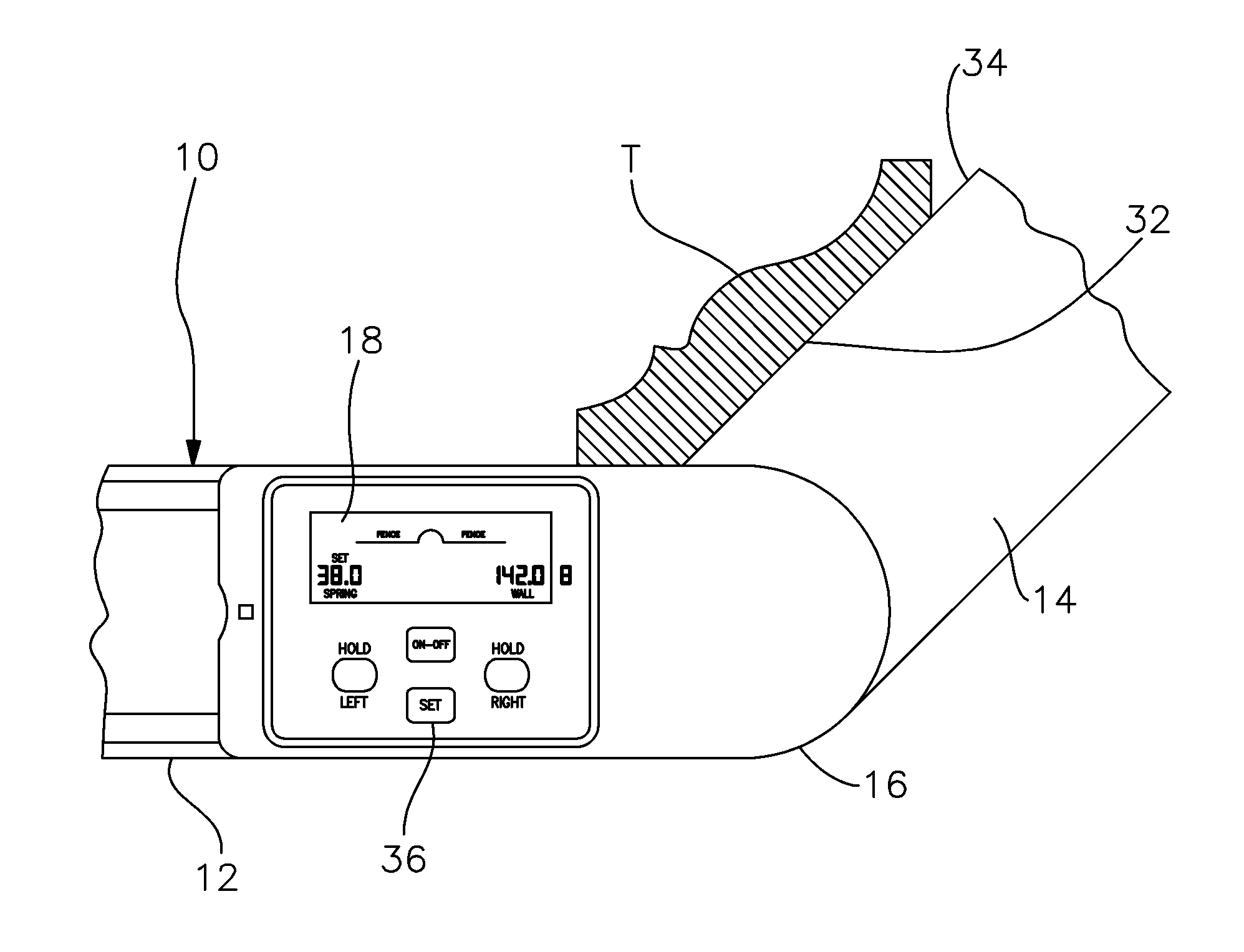
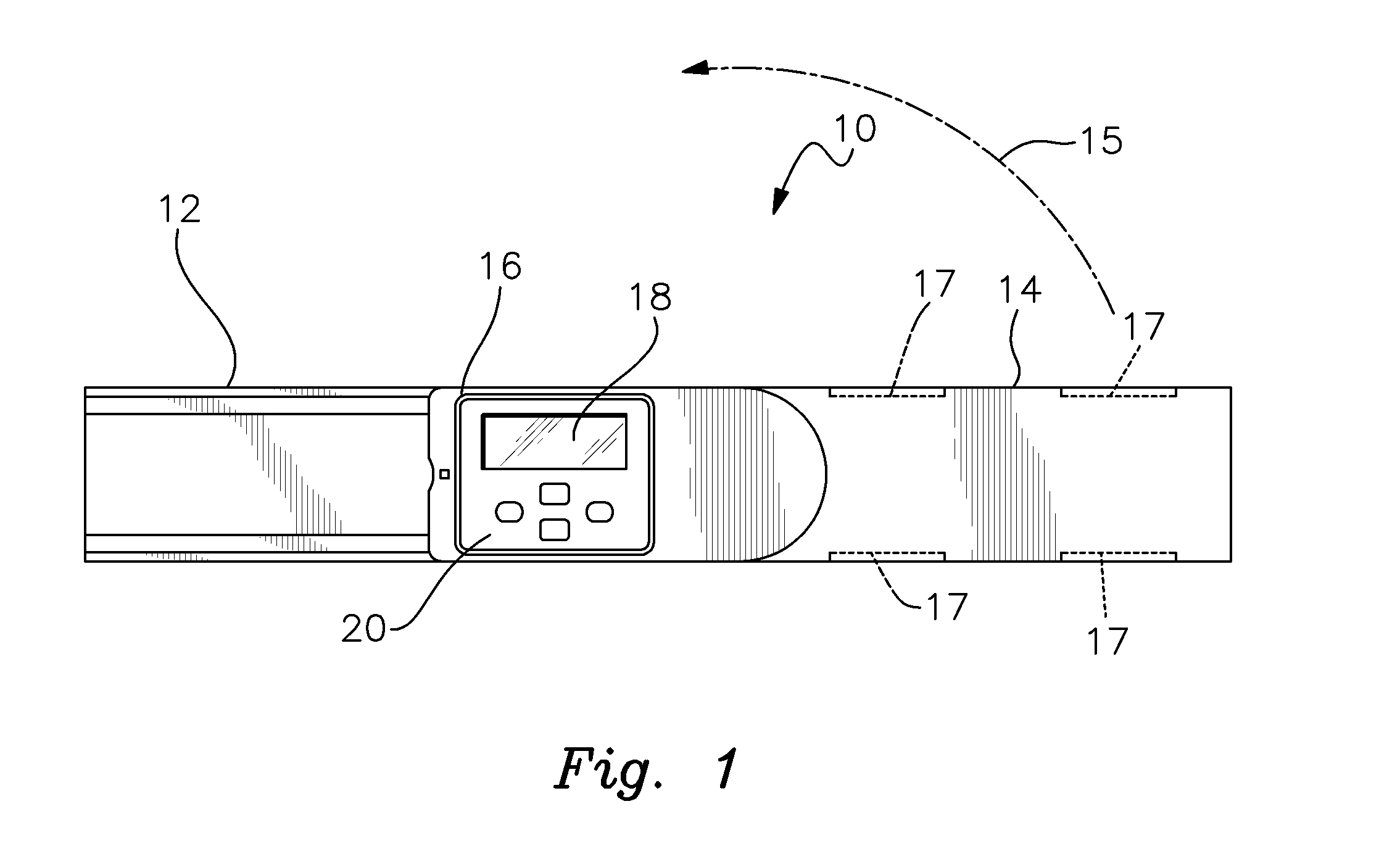
[0043]There is shown in FIG. 1 a protractor 10 that is used for both measuring both the spring and wall angles and for calculating and setting the corresponding miter and bevel angles needed to install adjoining pieces of molding and trim in crown molding and other carpentry applications. The particular environment and trim or molding application in which protractor 10 is employed are not limitations of this invention. Nonetheless, the protractor is especially useful for determining and setting the complex saw cut angles that must be formed in adjoining pieces of molding or trim used in crown molding and analogous applications where adjoining walls meet at a corner. As used herein, the terms “trim” and “molding” should be understood as being used interchangeably. Complex angles in adjoining pieces of trim are often required when those pieces meet at an inside or outside corner of a room or otherwise where two adjoining walls meet. The present invention enables both the wall angle an...


PUM


Abstract

A digital protractor is provided for measuring spring and wall angles and determining and effecting bevel and miter angle adjustments of a miter saw to adjoining pieces of trim in accordance with the measured spring and wall angles. The protractor includes a pair of pivotally interconnected arms. At least one sensor is attached to one of the arms and a digital readout is secured to the other arm. The readout includes means for determining the bevel and miter angles such that the protractor can be set to those angles to properly adjust the miter saw in accordance with the calculated angles.

Description

RELATED APPLICATION[0001]This application claims the benefit of U.S. Provisional Patent Application No. 62 / 125,093 filed Jan. 14, 2015.FIELD OF THE INVENTION[0002]This invention relates to a protractor that can be used to make measuring, cuffing and installing crown molding and other trim quicker, easier and more accurate.BACKGROUND OF THE INVENTION[0003]Crown molding and other types of decorative molding and trim can be extremely difficult, tedious and frustrating to install. Precisely mitered and beveled angles are typically required where adjoining pieces of molding or trim meet at inside and outside corners of adjacent walls. Forming these angles, especially when crown molding is involved, requires that complex cuts be made in the adjoining pieces of molding typically using a compound miter saw. Wall and spring angles must be measured, bevel and miter measurements calculated and the installer's saw precisely adjusted to achieve an accurate fit. This is traditionally a tedious, t...

Claims


Application Information

Patent Timeline
IPC IPC(8): G01B3/56E04F19/02E04F21/00
CPCG01B3/563E04F19/02E04F21/00E04F21/0069
Inventor WIXEY, BARRY DOUGLASJIAN, SHIJIN, LI GUANG
Owner WIXEY BARRY DOUGLAS
Why Eureka
Try Eureka