Noise reduction device and noise reduction system

a noise reduction device and noise reduction technology, applied in the field of seat noise reduction, can solve the problems of less convenient use of usage sites, less noise environment for users, and difficulty in adjusting the seat position, so as to maximize the noise reduction effect, reduce the effect of noise, and reduce the effect of maintenan

Active Publication Date: 2020-06-09
PANASONIC INTELLECTUAL PROPERTY MANAGEMENT CO LTD
View PDF19 Cites 0 Cited by
  • Summary
  • Abstract
  • Description
  • Claims
  • Application Information

AI Technical Summary

Benefits of technology

[0033]With the present disclosure, a seat can be put in its actual usage state, the acoustic transfer function can be calculated accurately and quickly without being affected by external noise, the self-testing of the functions constituting the system can be carried out, and these can be carried out safely during maintenance. This makes it possible to provide a noise reduction device and a noise reduction system that maximize the noise reduction effect.

Problems solved by technology

When providing information such as passenger announcement or audio entertainment service to a user sitting in a seat in an aircraft, a vehicle, or the like where there is a lot of noise, ambient noise at the seat can be a problem.
When using an internal space bounded by continuous walls, such as in an aircraft or a vehicle, the usage site is a kind of sealed structure, and if there are noise sources inside and outside the usage site, the noise environment ends up becoming entrenched for the user.
Therefore, depending on the level of noise, the noise can become a physical and mental constraint factor to the user, making the usage site less convenient to use.
In particular, when providing services to customers in the passenger compartment of an aircraft or the like, if convenience declines, this can seriously impede the quality of service business.
Especially in the case of an aircraft, the main sources of noise are those involving the noise of machinery used for generating thrust in the aircraft, such as propellers and engines, and sounds related to air flow generated by the movement of the aircraft through air layers, such as wind noise produced by the front end of the aircraft and by the wings during flight, so noise inside the aircraft is unpleasant to the passengers, and also hinders voice announcements and the like, so improvement is strongly desired.
Materials that are acoustically absorbent generally have higher density, and high-density materials lead to increased weight.
As the weight increases, fuel consumption increases and the cruising distance decreases.
Therefore, this diminishes the economic efficiency and functionality of the aircraft.
Also, if used as a structural material, the deterioration of function in terms of strength (prone to scratching, etc.) and design (texture and the like) cannot be ignored.

Method used


Image

  • Noise reduction device and noise reduction system
  • Noise reduction device and noise reduction system
  • Noise reduction device and noise reduction system

Examples


embodiment 1

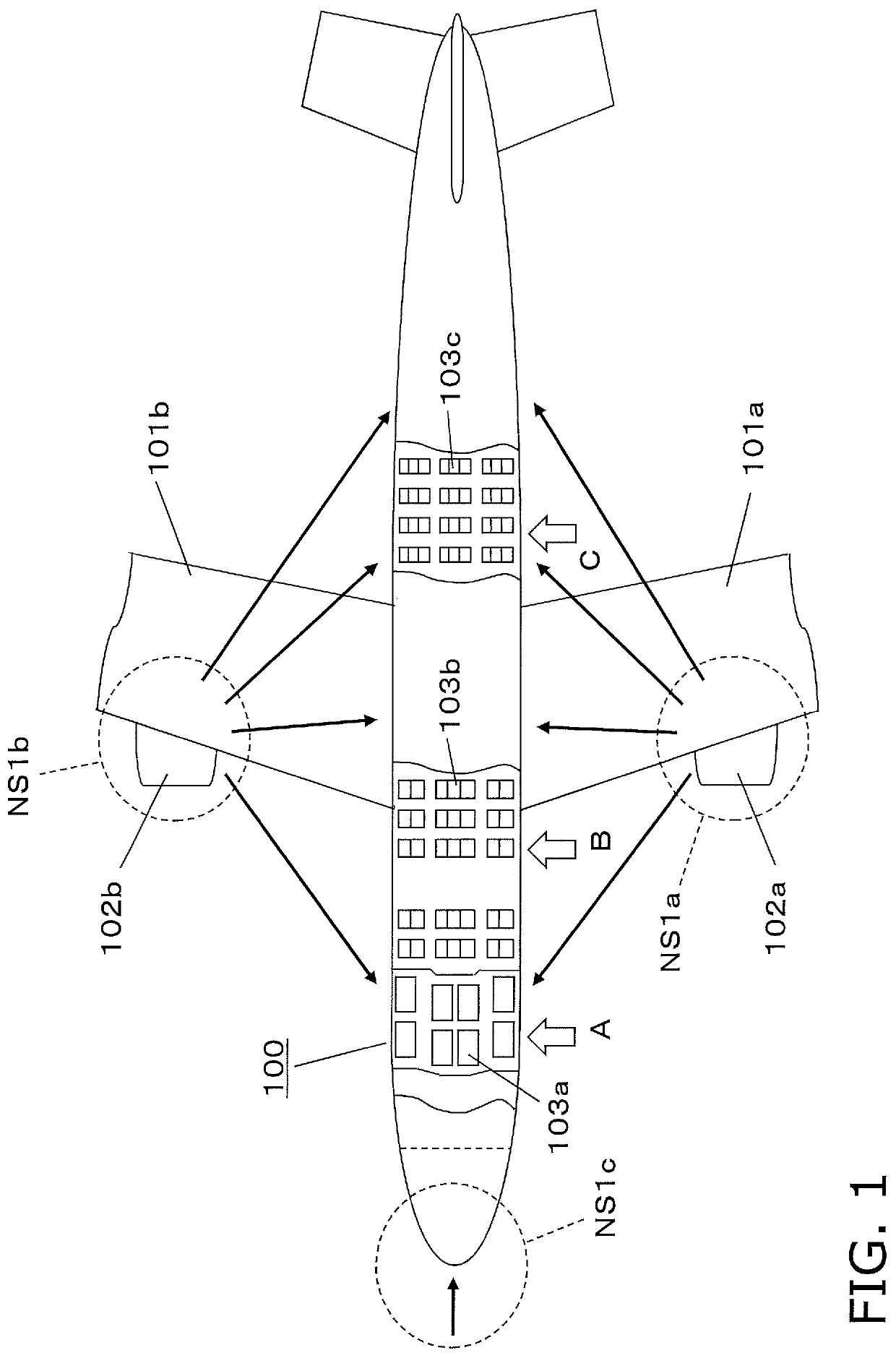
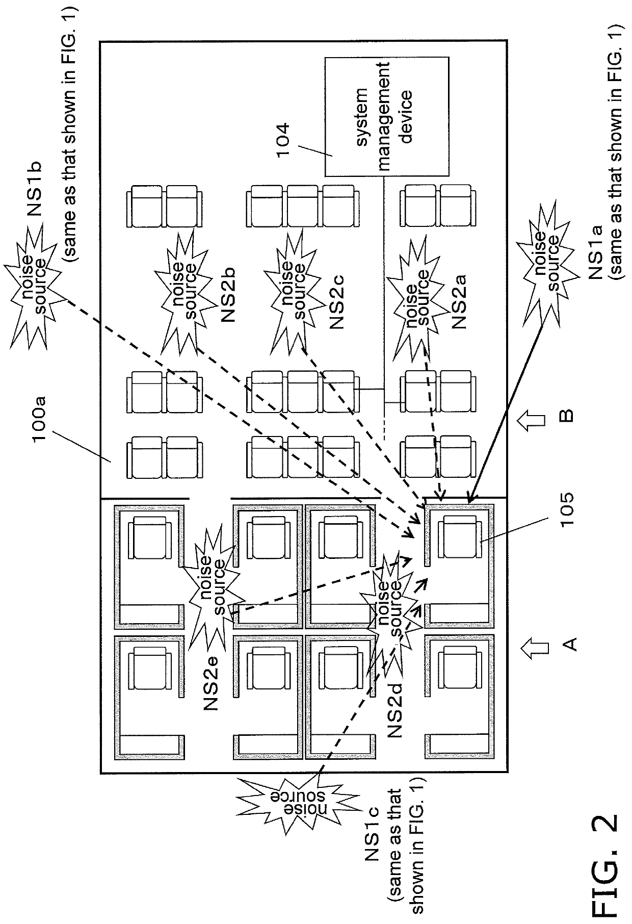
[0059]A noise reduction device in an embodiment of the present disclosure will now be described by citing a case in which the device is mounted in an aircraft. First, the acoustic environment in the aircraft requiring installation of noise reduction devices will be described through reference to FIGS. 1 and 2.

[0060]FIG. 1 is a plan view showing the installation environment of noise reduction devices in an embodiment of the present disclosure. As shown in FIG. 1, an aircraft 100 comprises engines 102a and 102b on left and right wings.

[0061]From the standpoint of the acoustic environment of an aircraft, the engines play a major role as a source of noise not only because of their running noise, but also because of reverberations of air flow during the flight and so forth. From the standpoint of passenger service, the engines 102a and 102b are external noise sources NS1a and NS1b that affect parts of the aircraft located at seat rows 103a, 103b, and 103c installed in a cabin A (such as ...

embodiment 2

[0107]FIG. 10 is a flowchart illustrating an operation example of the noise reduction device in Embodiment 2 of the present disclosure.

[0108]In this embodiment, a plurality of noise reduction devices are installed in each seat of an aircraft to constitute a noise reduction system.

[0109]In this flowchart, the operation at each seat is illustrated in an example in which information between the plurality of seats shown in FIG. 11 is managed by a server (system management device; not shown). In FIG. 11, the seats are numbered from rows one to four from front to rear, and the lines of seats are lettered line A, line C, . . . , line K from left to right. For example, the left-front seat is called seat 1A, and the seat in row 2 and line H is called seat 2H. The steps of the flowchart shown in FIG. 10 will be described below.

[0110]When the power to the noise reduction device is turned on, the flow proceeds from step S010 to step S011. In step S011, it is determined whether or not identifica...

third embodiment

[0135]FIG. 19 is a block diagram showing the basic configuration for performing the identification operation with the noise reduction device in an embodiment of the present disclosure.

[0136]In carrying out an identification operation for each noise reduction device, the system management device 501 first notifies the seat driver 581 to create a seat actual usage state in which noise reduction effectively acts at each seat.

[0137]For example, if the fully reclined bed mode, in which the seat is reclined horizontally for sleeping, is the actual usage state of noise reduction, the seat driver 581 puts the seat in bed mode.

[0138]When the identification operation is commenced at each seat, the identification controller 538 starts the identification operation after the seat detector 582 has detected that the seat is in the actual usage state of noise reduction.

[0139]The seat detector 582 may detect that a seat has been fully reclined and is in the bed mode position, or may detect that the ...


PUM


Abstract

With the noise reduction device (300), in identifying an acoustic transfer function that includes a path from the control speaker (340) to the error microphone (350) or the noise microphone (320) by outputting an identification sound from the control speaker (340) and detecting the identification sound with the error microphone (350) or the noise microphone (320), the identification controller (338) is configured to identify the acoustic transfer function by generating the identification sound from the white noise generator (337) when the seat detector (582) has detected that the seat is in the actual usage state for noise reduction.

Description

TECHNICAL FIELD[0001]The present disclosure relates to the reduction of noise in a seat, and more particularly relates to a noise reduction device and noise reduction system that are used in aircraft, railway cars, and the like.BACKGROUND ART[0002]When providing information such as passenger announcement or audio entertainment service to a user sitting in a seat in an aircraft, a vehicle, or the like where there is a lot of noise, ambient noise at the seat can be a problem. When using an internal space bounded by continuous walls, such as in an aircraft or a vehicle, the usage site is a kind of sealed structure, and if there are noise sources inside and outside the usage site, the noise environment ends up becoming entrenched for the user. Therefore, depending on the level of noise, the noise can become a physical and mental constraint factor to the user, making the usage site less convenient to use. In particular, when providing services to customers in the passenger compartment of...

Claims


Application Information

Patent Timeline
Patent Type & Authority Patents(United States)
IPC IPC(8): G10K11/178B64D11/06B60R13/08B61D49/00B64C1/40H04R3/00H04R5/02
CPCB64D11/06G10K11/17817G10K11/17819B61D49/00G10K11/17813B60R13/0815B64C1/40H04R3/005G10K2210/3023G10K2210/3049G10K2210/3055H04R5/023H04R2410/05G10K2210/3035G10K2210/1281G10K2210/128G10K2210/504B64D11/0015B64D11/00154B64D11/0602Y02T50/40
Inventor KUBOTA, KENICHI
Owner PANASONIC INTELLECTUAL PROPERTY MANAGEMENT CO LTD
Why Eureka
Try Eureka