Object Detector

Active Publication Date: 2016-08-18
HITACHI ASTEMO LTD
View PDF4 Cites 18 Cited by
  • Summary
  • Abstract
  • Description
  • Claims
  • Application Information

AI Technical Summary

Benefits of technology

[0008]By extracting an object existing in the long distance region away from the vehicle and having a specific color (for example, a preceding vehicle with a brake light (brake lamp), a tail light (tail lamp), an auxiliary brake light (high mounted stop lamp), or the like turned on) from among objects in an image and by outputting distance information to the object that has been extracted, the object detector according to the present invention is capable of suppressing the noise in the long distance region and

Problems solved by technology

In recent years, downsizing of the stereo camera has been demanded in particular; however, there is a problem in that a decr

Method used


Image

  • Object Detector
  • Object Detector
  • Object Detector

Examples


first embodiment

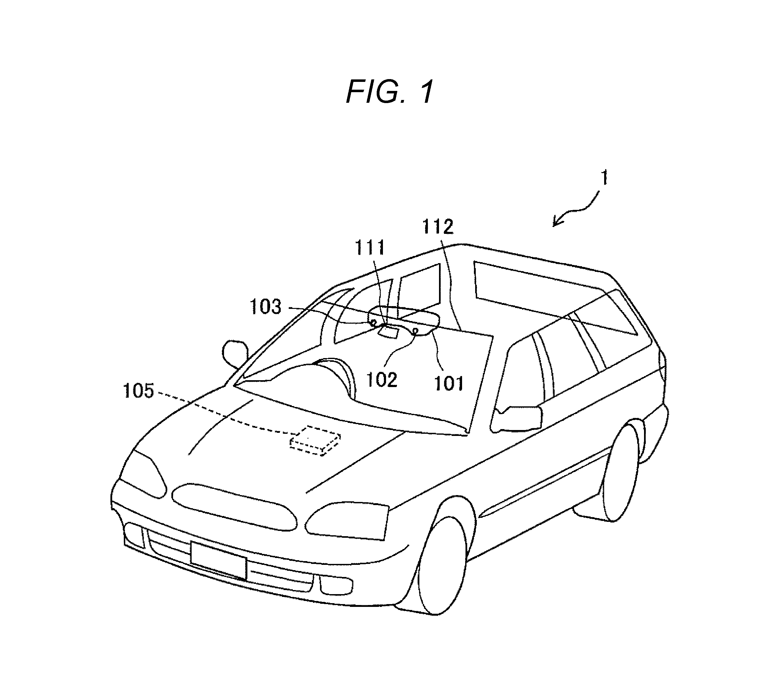
[0019]FIG. 1 is a view schematically illustrating a vehicle to which an object detector according to a first embodiment of the present invention is applied.

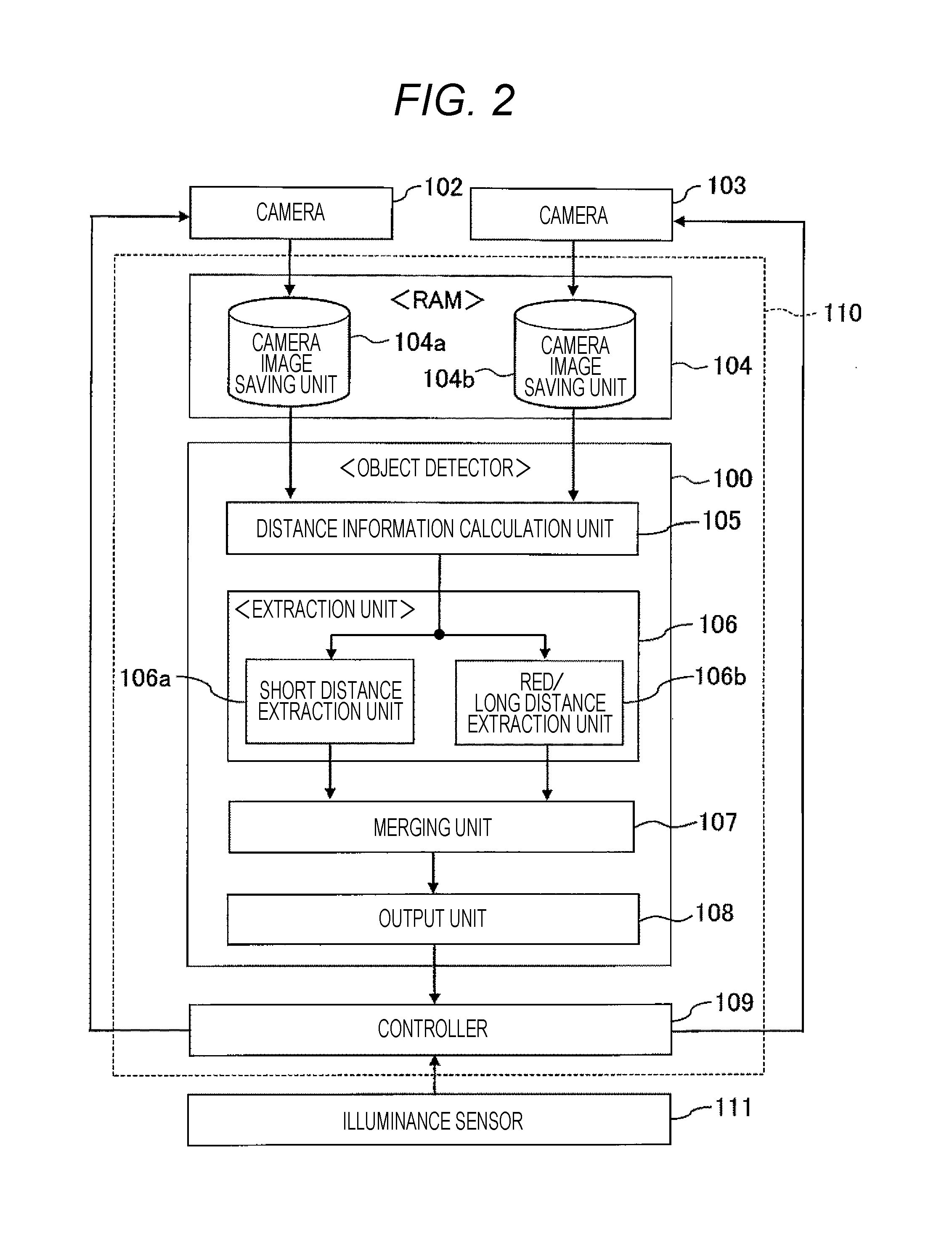
[0020]To a vehicle 1 in FIG. 1, two cameras (imaging units) 102 and 103 are disposed at a predetermined position (for example, a room mirror 101 of the vehicle 1) of the vehicle 1 side by side in a horizontal direction and facing frontward of the vehicle 1. To the vehicle 1, an illuminance sensor 111 that detects illuminance around the vehicle 1 is disposed at a predetermined position (for example, an upper part of a front window 112 of the vehicle 1). The two cameras 102 and 103 and the illuminance sensor 111 are communicably connected to a control unit 110 incorporating an object detector 100 (see FIG. 2), whereby an image obtained by the cameras 102 and 103 and illuminance information detected by the illuminance sensor 111 are transmitted to the control unit 110 through a connecting wire (not illustrated), for example.
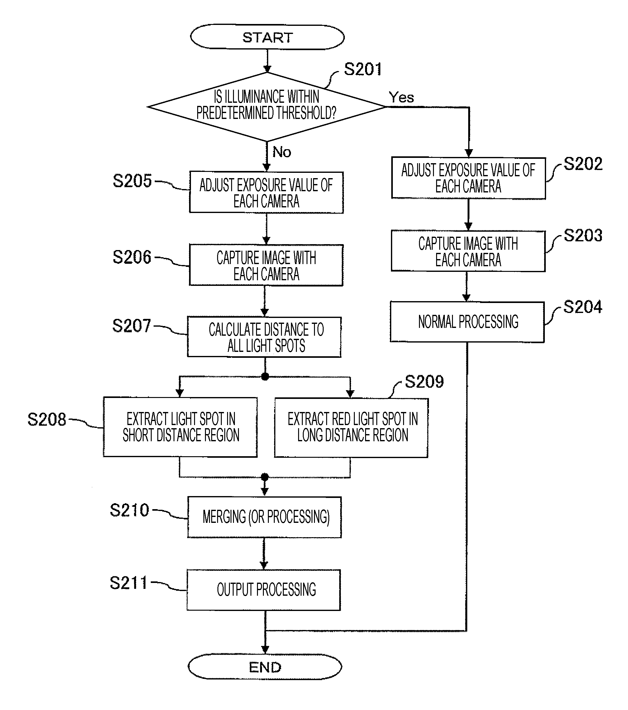
[0021]FI...

second embodiment

[0037]FIG. 6 is a diagram illustrating an internal configuration of a control unit in which an object detector according to a second embodiment of the present invention is incorporated. An object detector 100A according to the second embodiment has an extraction unit having a different configuration from that of the object detector 100 according to the first embodiment; however, any other configuration is identical to that of the object detector 100 according to the first embodiment. Thus, the configuration identical to that of the object detector 100 according to the first embodiment is denoted by the same reference numeral, and a detailed description thereof is omitted herein.

[0038]The object detector 100A according to the second embodiment mainly includes a distance information calculation unit 105A, an extraction unit 106A, a merging unit 107A, and an output unit 108A. The extraction unit 106A includes a short distance extraction unit 106aA and a red color extraction unit 106bA....

third embodiment

[0049]FIG. 8 is a diagram illustrating an internal configuration of a control unit in which an object detector according to a third embodiment of the present invention is incorporated. An object detector 100B according to the third embodiment is different from the object detector 100A according to the second embodiment in that the object detector has an exposure value adjustment function; however, any another configuration is identical to that of the object detector 100A according to the second embodiment. Thus, the configuration identical to that of the object detector 100A according to the second embodiment is denoted by the same reference numeral, and a detailed description thereof is omitted herein.

[0050]The object detector 100B according to the third embodiment mainly includes a distance information calculation unit 105B, an extraction unit 106B, a merging unit 107B, an output unit 108B, and an exposure value adjustment unit 112B that generates a control signal for performing e...


PUM


Abstract

Provided is an object detector capable of suppressing any decrease in accuracy of object detection under a low illuminance environment such as nighttime or in tunnels, whereby suppressing a failure of Adaptive Cruise Control, pre-crash safety systems, and the like. The object detector includes: a distance information calculation unit 105 configured to calculate distance information to an object around a vehicle from an image captured by a plurality of imaging units 102, 103; an extraction unit 106 configured to extract at least an object existing in a long distance region away from the vehicle and having a specific color from among objects in the image based on the distance information; and an output unit 108 configured to output the distance information to the object having been extracted by the extraction unit 106.

Description

TECHNICAL FIELD[0001]The present invention relates to an object detector, and in particular, relates to an object detector for detecting a preceding vehicle ahead of a vehicle under a low illuminance environment such as nighttime.BACKGROUND ART[0002]In an automobile field, for purposes of supporting driving, improving safety, and the like, various kinds of research and development have been made such as on an Adaptive Cruise Control (ACC) and pre-crash safety systems. The ACC and the pre-crash safety systems are techniques of capturing an image ahead of a vehicle with a stereo camera mounted on the vehicle, measuring a relative distance to a preceding vehicle from the captured image, and allowing the vehicle to follow the preceding vehicle or to brake predicting a collision against the preceding vehicle.[0003]In a case where the relative distance to the preceding vehicle is measured from the image obtained with the stereo camera, the relative distance between the vehicles or the lik...

Claims


Application Information

Patent Timeline
IPC IPC(8): G08G1/16H04N13/02G06T7/00G06T7/40G06K9/00H04N5/243H04N13/239
CPCG06K9/00805G08G1/166G08G1/167G06T2207/30261G06T2207/30236H04N13/0239G06T2207/10024G06T7/408G06T7/0042H04N5/243G06T2207/10028H04N13/239G06V20/584G06V20/58H04N23/76
Inventor OTSUKA, YUJI
Owner HITACHI ASTEMO LTD
Why Eureka
Try Eureka