Light emitting component

a technology of light emitting components and components, applied in the direction of basic electric elements, electrical equipment, semiconductor devices, etc., can solve the problems of ineffective enhancement of the entire light emitting efficiency of the light emitting component b>1/b>, unstable silver and random diffusion under high temperature, etc., to achieve enhanced light emitting efficiency of the light emitting component, less active chemical properties, and effective increase of the total reflective area

Inactive Publication Date: 2016-08-18
GENESIS PHOTONICS
View PDF4 Cites 9 Cited by
  • Summary
  • Abstract
  • Description
  • Claims
  • Application Information

AI Technical Summary

Benefits of technology

[0006]The disclosure provides a light emitting component capable of increasing a reflective area effectively, so as to solve the aforementioned problems.
[0010]As to the above mentioned, the disclosure provides to dispose the second reflective layer on the first reflective layer and extend the second reflective layer to the adhesive layer, such that the projection area of the second reflective layer is larger than the projection area of the first reflective layer. In other words, the disclosure provides that the first reflective layer with active chemical property (e.g. silver or silver alloy) is disposed on the adhesive layer within a certain area in advance, so as to prevent from the material of the first reflective layer diffusing to the epitaxial structure due to elevated temperature during manufacture process. Then, the second reflective layer with less active chemical property (e.g. non-silver metal, non-silver alloy or insulating material) is disposed on the first reflective layer and is extended onto the adhesive layer. Accordingly, the disclosure provides that the entire light emitting efficiency of the light emitting component can be enhanced by using the second reflective layer to increase the total reflective area effectively.

Problems solved by technology

Since the chemical property of silver is very active, silver is unstable and diffuses randomly under high temperature.
Accordingly, the reflective area of the reflective layer 14 is also limited to reflect limited light, such that the entire light emitting efficiency of the light emitting component 1 cannot be enhanced effectively.

Method used


Image

  • Light emitting component
  • Light emitting component
  • Light emitting component

Examples


first embodiment

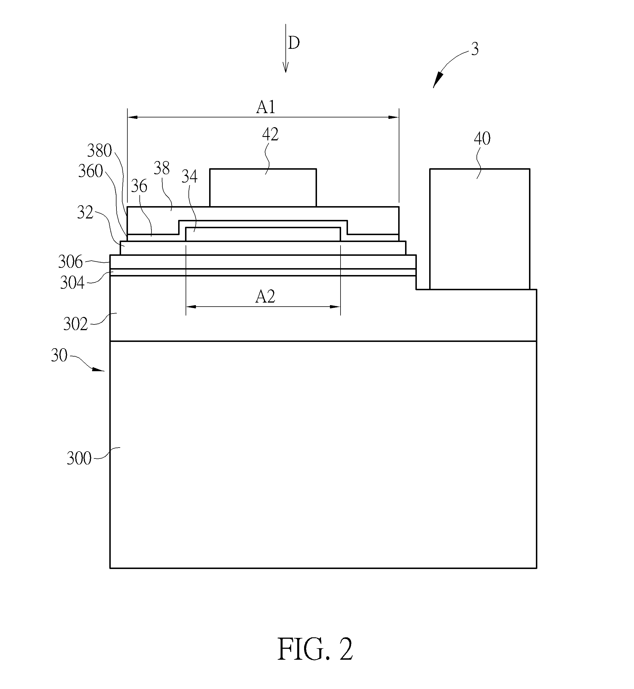
[0017]Referring to FIG. 2, FIG. 2 is a schematic view illustrating a light emitting component 3 according to the disclosure. As shown in FIG. 2, the light emitting component 3 comprises an epitaxial structure 30, an adhesive layer 32, a first reflective layer 34, a second reflective layer 36, a block layer 38, a first electrode 40 and a second electrode 42. The epitaxial structure 30 comprises a substrate 300, a first semiconductor layer 302, a light emitting layer 304 and a second semiconductor layer 306, wherein the first semiconductor layer 302 is located on the substrate 300, the light emitting layer 304 is located on the first semiconductor layer 302, and the second semiconductor layer 306 is located on the light emitting layer 304. A material of the substrate 300 may be, but not limited to, a sapphire. The first electrode 40 is electrically connected to the first semiconductor layer 302 and the second electrode 42 is electrically connected to the second semiconductor layer 306...

second embodiment

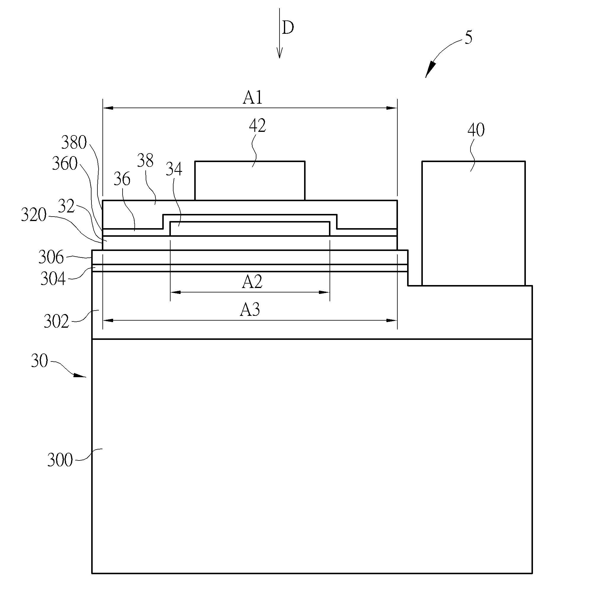
[0021]Referring to FIG. 3 along with FIG. 2, FIG. 3 is a schematic view illustrating a light emitting component 5 according to the disclosure. The main difference between the light emitting component 5 and the aforementioned light emitting component 3 is that, in the light emitting component 5, the side surface 360 of the second reflective layer 36, the side surface 380 of the block layer 38 and a side surface 320 of the adhesive layer 32 are planar. In other words, the projection area A1 of the second reflective layer 36 in the projection direction D may be equal to a projection area A3 of the adhesive layer 32 in the projection direction D, and the ratio of the projection area A2 of the first reflective layer 34 in the projection direction D to the projection area A4 of the light emitting layer 304 in the projection direction D is smaller than 30%. In an embodiment, the ratio of the projection area A2 of the first reflective layer 34 in the projection direction D to the projection...

third embodiment

[0022]Referring to FIG. 4 along with FIG. 3, FIG. 4 is a schematic view illustrating a light emitting component 7 according to the disclosure. The main difference between the light emitting component 7 and the aforementioned light emitting component 5 is that the second reflective layer 36 of the light emitting component 7 is further extended onto the second semiconductor layer 306 of the epitaxial structure 30, such that the projection area A1 of the second reflective layer 36 in the projection direction D is larger than the projection area A3 of the adhesive layer 32 in the projection direction D, and the ratio of the projection area A2 of the first reflective layer 34 in the projection direction D to the projection area A4 of the light emitting layer 304 in the projection direction D is smaller than 30%. In one embodiment, the ratio of the projection area A2 of the first reflective layer 34 in the projection direction D to the projection area A4 of the light emitting layer 304 in...


PUM


Abstract

A light emitting component includes an epitaxial structure, an adhesive layer, a first reflective layer, a second reflective layer, a block layer, a first electrode and a second electrode. The epitaxial structure includes a substrate, a first semiconductor layer, a light emitting layer and a second semiconductor layer. The adhesive layer is disposed on the second semiconductor layer of the epitaxial structure. The first reflective layer is disposed on the adhesive layer. The second reflective layer is disposed on the first reflective layer and extended onto the adhesive layer. A projection area of the second reflective layer is larger than a projection area of the first reflective layer. The block layer is disposed on the second reflective layer. The first electrode is electrically connected to the first semiconductor layer. The second electrode is electrically connected to the second semiconductor layer.

Description

CROSS REFERENCE TO RELATED APPLICATION[0001]This application claims the benefit of U.S. Provisional Application No. 62 / 116,923, which was filed on Feb. 17, 2015, and is incorporated herein by reference.BACKGROUND OF THE INVENTION[0002]1. Field of the Invention[0003]The disclosure relates to a light emitting component and, more particularly, to a light emitting component capable of increasing a reflective area effectively.[0004]2. Description of the Prior Art[0005]Referring to FIG. 1, FIG. 1 is a schematic view illustrating a light emitting component 1 of prior art. As shown in FIG. 1, the light emitting component 1 comprises an epitaxial structure 10, an ohmic contact layer 12, a reflective layer 14, a block layer 16 and two electrodes 18, wherein the ohmic contact layer 12, the reflective layer 14, the block layer 16 and the electrodes 18 are disposed on the epitaxial structure 10. The reflective layer 14 is used to reflect light emitted by a light emitting layer 100 of the epitaxi...

Claims


Application Information

Patent Timeline
Patent Type & Authority Applications(United States)
IPC IPC(8): H01L33/10
CPCH01L33/382H01L33/56H01L33/507H01L33/52H01L2933/0025H01L2933/005H01L2933/0058H01L33/10H01L25/0753H01L33/62H01L33/58H01L33/54H01L33/42H01L33/20H01L33/0095H01L2933/0016H01L33/46H01L33/405H01L2224/48091H01L2224/48247H01L2224/48257H01L2224/49107H01L2224/73265H01L2924/00014
Inventor HUANG, YI-RUCHUANG, TUNG-LINSHEN, CHIH-MINGHSU, SHENG-TSUNGHUANG, KUAN-CHIEHHUANG, JING-EN
Owner GENESIS PHOTONICS
Why Eureka
Try Eureka