Power management system, power management method, and computer program

Active Publication Date: 2016-08-18
PANASONIC INTELLECTUAL PROPERTY MANAGEMENT CO LTD
View PDF3 Cites 5 Cited by
  • Summary
  • Abstract
  • Description
  • Claims
  • Application Information

AI Technical Summary

Benefits of technology

[0006]It is an object of the present invention to provide a power management system, which can provide a motivation for promoting use of a power storage a

Problems solved by technology

Incidentally, in a consumer's facility, a cost at introduction of a storage battery (power storage apparatus) capable of supplying power to an electric load is high.
The high cost is a factor in a hindrance to spreading a power storage apparatus.
Supplyin

Method used


Image

  • Power management system, power management method, and computer program
  • Power management system, power management method, and computer program
  • Power management system, power management method, and computer program

Examples


embodiment 1

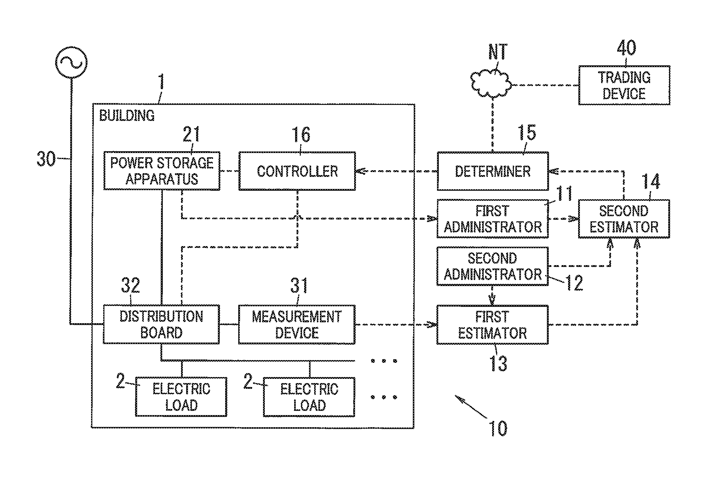
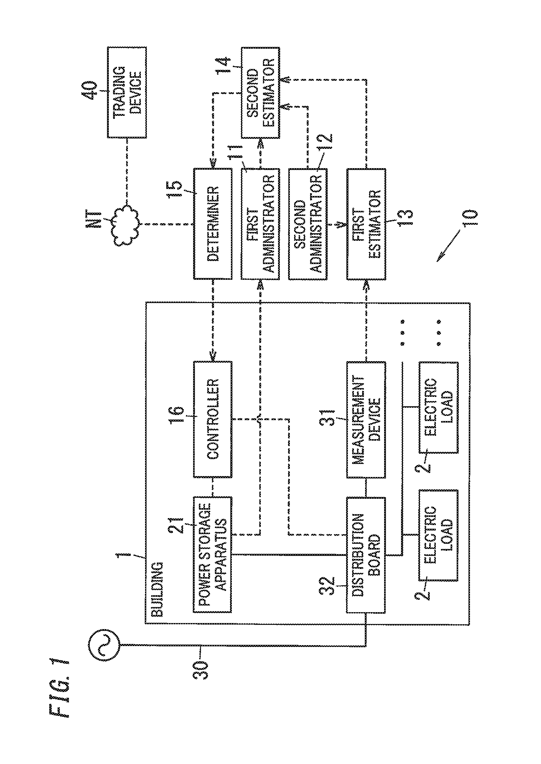
[0030]In this embodiment, as shown in FIG. 1, a case will be described, where two or more electric loads 2 (two in FIG. 1) that consume power and a power storage apparatus 21 capable of supplying power to a power grid 30 are provided in a consumer's building 1. In other words, only the power grid 30 and the power storage apparatus 21 supply power to the electric loads 2 in the building 1. A distribution board 32 is installed in the consumer's building 1. The power grid 30, the power storage apparatus 21 and the electric loads 2 are connected to the distribution board 32.

[0031]The distribution board 32 includes: a principal circuit (not shown) that receives power from the power grid 30; and a plurality of branch circuits (not shown) that are branched from the principal circuit and constitute a plurality of systems. In other words, in the distribution board 32, an electric path is branched to form the branch circuits so as to supply power received from the power grid 30 to the electri...

embodiment 2

[0064]In this embodiment, as shown in FIG. 4, a case will be described, where a photovoltaic power generation apparatus 22 is installed in a building 1 in addition to a power storage apparatus 21. The photovoltaic power generation apparatus 22 does not need a consideration of charging, unlike the power storage apparatus 21, however, power generated by it is not constant. That is, power that can be output changes every moment, depending on a temperature, and intensity, an incident angle, a wavelength component and the like, of light that is incident on a solar cell constituting the photovoltaic power generation apparatus 22. Also, the photovoltaic power generation apparatus 22 is not configured to output a fixed voltage, but configured such that an output voltage thereof follows a line voltage of electric lines connected to the photovoltaic power generation apparatus 22. In other words, when the generated power is changed while power is received from the power grid 30, the output vol...


PUM


Abstract

A power management system includes a first administrator, a second administrator, a first estimator, a second estimator and a determiner. The first administrator manages a residual capacity of a power storage apparatus. The second administrator manages interruption information regarding a power grid. The first estimator estimates, as first power information, an amount of power that is consumed by an electric load during an interruption period. The second estimator estimates an estimation residual capacity that is the residual capacity at an end point of the interruption period, based on the first power information. The determiner determines that a condition for participating in a power trade market is met, when the estimation residual capacity exceeds a reference value.

Description

TECHNICAL FIELD[0001]The invention relates generally to power management systems, power management methods and computer programs and, more particularly, to a power management system configured to manage electric power that is output from a power storage apparatus installed within a consumer's building or around the building, a power management method for the power management system, and a computer program for realizing the power management system.BACKGROUND ART[0002]There has been recently provided a power storage apparatus to be used in a consumer's facility. This type of power storage apparatus is used to be charged while a power grid is in a normal state and supply power to electric loads while the power grid is in a service interruption state.[0003]For example, JP 2012-228043 A (hereinafter, referred to as “Document 1”) discloses a technique of: acquiring interruption schedule period information that indicates an interruption schedule period, determined by planned outage; and pe...

Claims


Application Information

Patent Timeline
IPC IPC(8): H02J3/00G06Q50/06G06Q40/04
CPCG06Q50/06H02J3/008H02J2003/003Y04S10/60G06Q40/04Y04S50/10Y04S10/54G06Q10/06H02J3/32Y02P90/90H02J3/003Y04S10/50
Inventor TOKUNAGA, YOSHIHIKOMIYAZAKI, SEIICHIFUKUDA, NAOHIROKURIYAMA, HIROYUKIOTA, NORIMASA
Owner PANASONIC INTELLECTUAL PROPERTY MANAGEMENT CO LTD
Why Eureka
Try Eureka