Piezoelectric drive device, robot, and drive method thereof

a technology of piezoelectric drive and robot, which is applied in the direction of piezoelectric/electrostrictive/magnetostrictive devices, piezoelectric/electrostriction/magnetostriction machines, and program-controlled manipulators. it can solve the problems of insufficient study of the suitable configuration of a piezoelectric drive device with high output power, the proportional increase of the whole size of the piezoelectric drive device, and the inability to us

Active Publication Date: 2016-08-18
SEIKO EPSON CORP
View PDF13 Cites 14 Cited by
  • Summary
  • Abstract
  • Description
  • Claims
  • Application Information

AI Technical Summary

Benefits of technology

[0007]An advantage of some aspects of the invention is to solve at least a part of the problems described above, and the invention can be implemented as the following aspects or application examples.

Problems solved by technology

However, in this case, if the multiple piezoelectric drive devices which are used are treated as one piezoelectric drive device as a whole, a problem arises in that the whole size of the piezoelectric drive device increases in proportion to the number of the piezoelectric drive devices which are used.
Consequently, for example, since an arrangement space of a drive device is restricted as in a drive device for driving joints of a robot, there is a possibility that the piezoelectric drive device may be less likely to be employed as the drive device whose small size and high output power are desirable.
Therefore, a suitable configuration of a miniaturized and lightweight piezoelectric drive device having high output power has not been sufficiently studied.

Method used


Image

  • Piezoelectric drive device, robot, and drive method thereof
  • Piezoelectric drive device, robot, and drive method thereof
  • Piezoelectric drive device, robot, and drive method thereof

Examples


first embodiment

A. First Embodiment

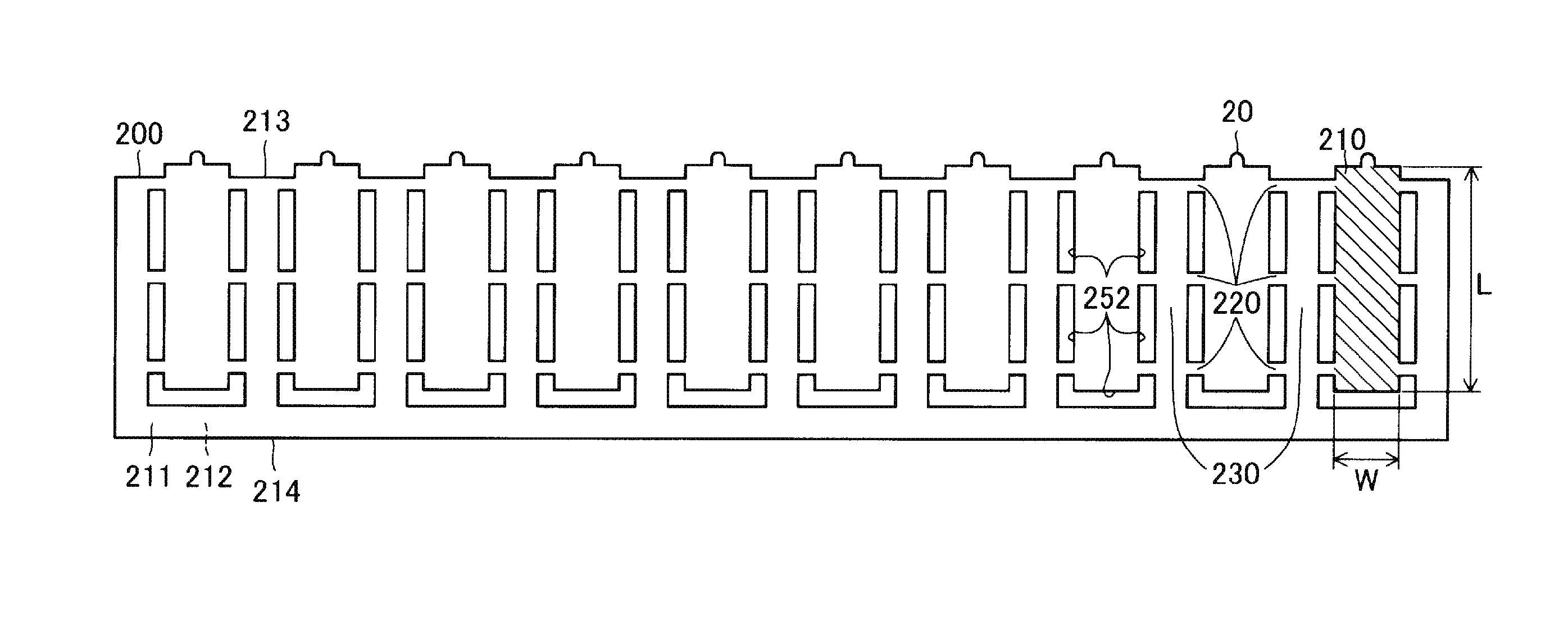
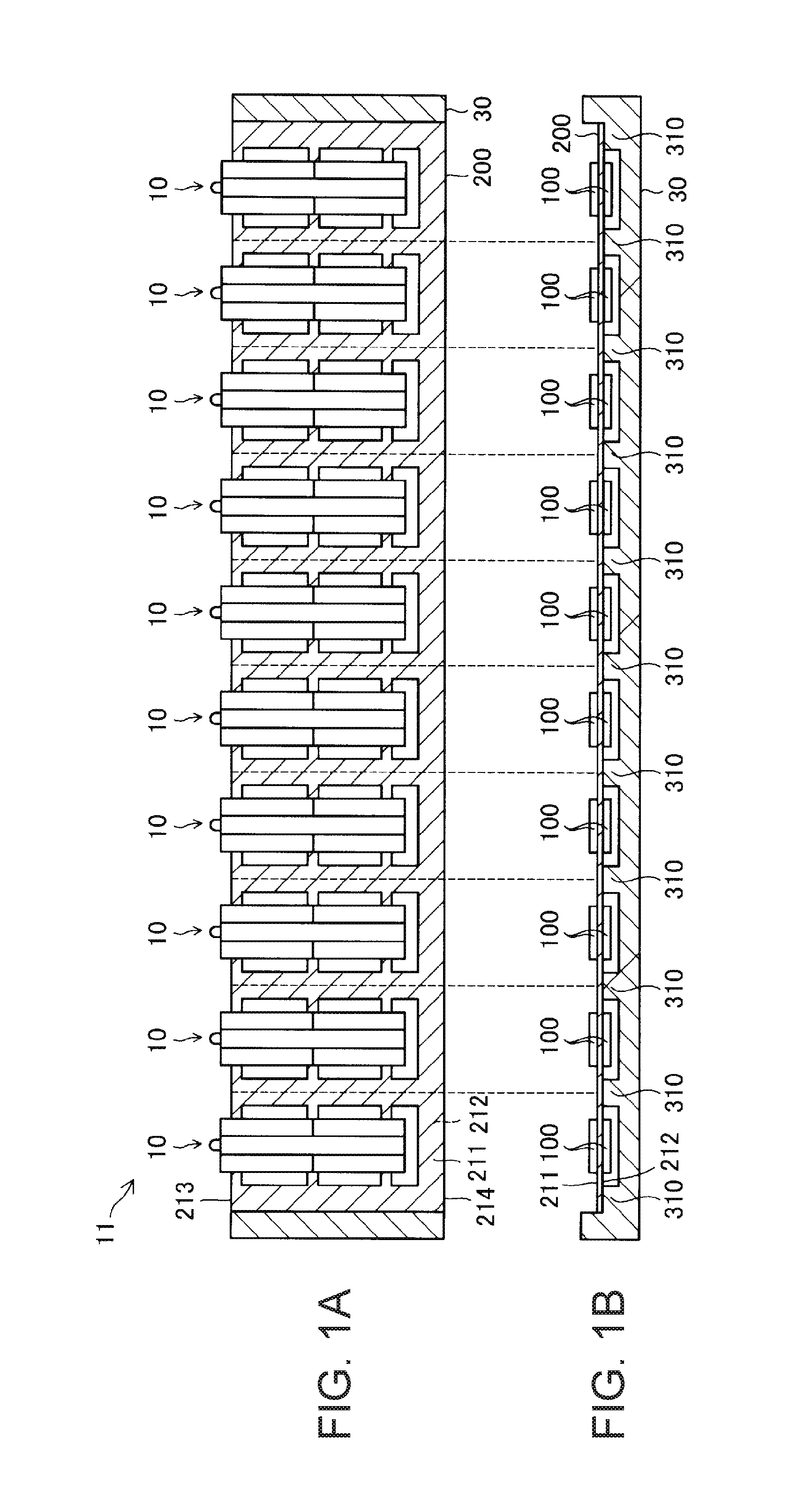
[0047]FIGS. 1A and 1B are schematic configuration diagrams of a piezoelectric drive device 11 according to a first embodiment of the invention. FIG. 1A is a plan view of the piezoelectric drive device 11, and FIG. 1B is a side view thereof. The piezoelectric drive device 11 includes a vibrating plate 200 and multiple piezoelectric drive units 10 arranged in the vibrating plate 200. The vibrating plate 200 having the piezoelectric drive units 10 arranged therein are supported by and fixed to each support portion 310 of a support body 30. The piezoelectric drive unit 10 includes two piezoelectric vibrating bodies 100 which are respectively arranged on both surfaces of the vibrating plate 200. In FIGS. 1A and 1B, for convenience of illustration, the vibrating plate 200 and the support body 30 are hatched.

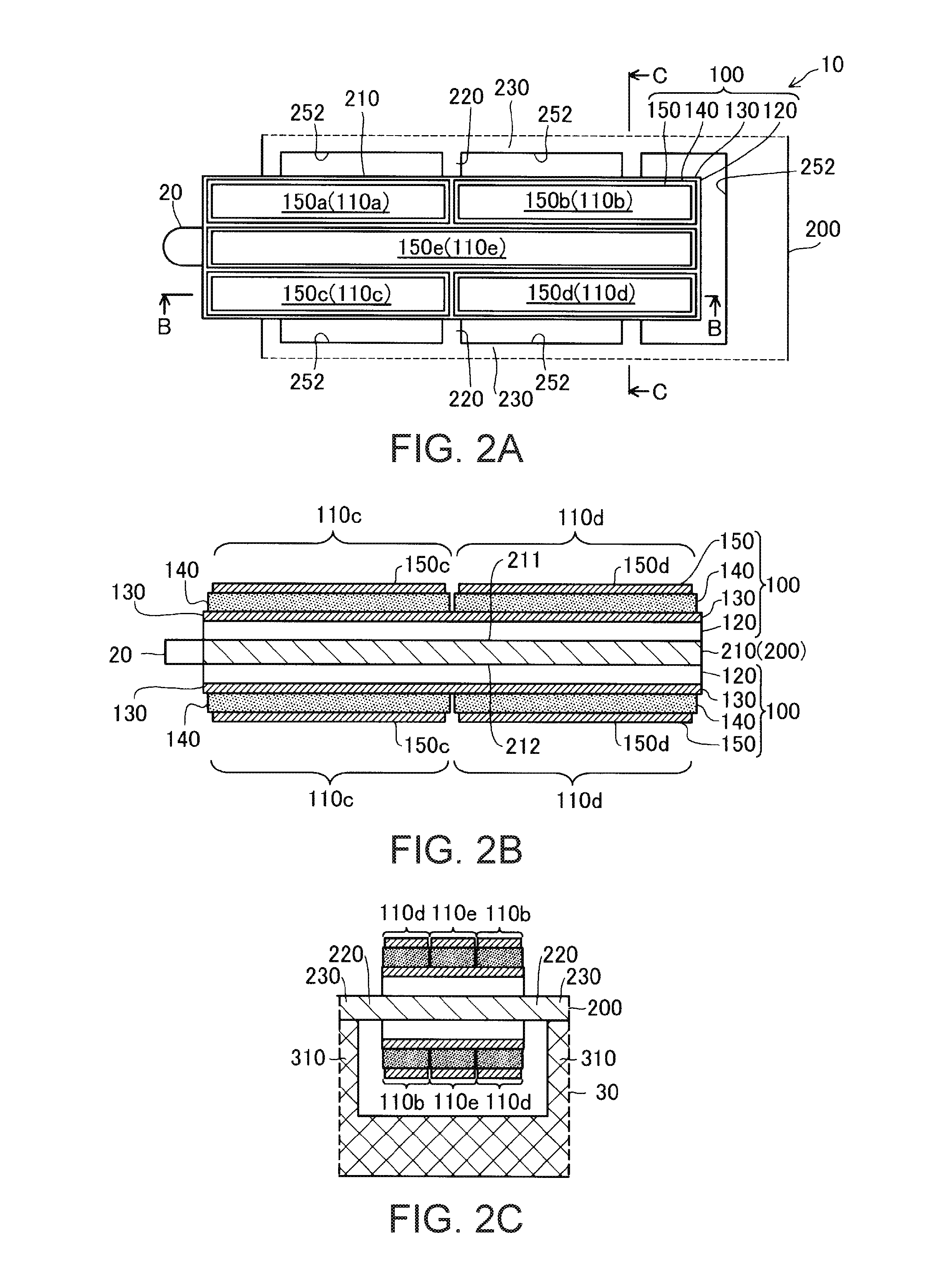
[0048]FIGS. 2A to 2C are schematic configuration diagrams of the piezoelectric drive unit 10. FIG. 2A is a plan view of the piezoelectric drive unit 10, FIG. 2B is a...

second embodiment

B. Second Embodiment

[0065]FIG. 7 is a side view illustrating a schematic configuration of a piezoelectric drive device 11C according to a second embodiment. Similarly to FIGS. 1A and 1B, in FIG. 7, for convenience of illustration, the vibrating plate 200 and the support body 30 are hatched. The piezoelectric drive device 11C is configured so that the piezoelectric drive device 11 (refer to FIGS. 1A and 1B) according to the first embodiment is stacked at multiple locations along a direction perpendicular to the surface (first surface 211 and the second surface 212) on which the piezoelectric drive unit 10 is arranged. That is, the piezoelectric drive device 11C has a layered structure in which the vibrating plate 200 having the multiple piezoelectric vibrating bodies 100 arranged therein is stacked via the support body 30 at multiple locations along the direction perpendicular to the surface on which the piezoelectric vibrating body 100 is arranged. The respective piezoelectric drive...

third embodiment

C. Third Embodiment

[0067]FIG. 8 is a plan view illustrating a schematic configuration of a piezoelectric drive device 11D according to a third embodiment. The piezoelectric drive device 11D has a configuration in which a first piezoelectric drive unit 10a having the protrusion portion 20 on a third surface 213 interposed between the first surface 211 and the second surface 212 in a vibrating plate 200D and a second piezoelectric drive unit 10b having the protrusion portion 20 on a fourth surface 214 opposing the third surface 213 are alternately arranged. Similarly to FIGS. 1A and 1B, in FIG. 8, for convenience of illustration, the vibrating plate 200D is hatched. However, the support body 30 is omitted.

[0068]A configuration of the first piezoelectric drive unit 10a and a configuration of the second piezoelectric drive unit 10b are the same as that of the piezoelectric drive unit 10 according to the first embodiment. However, in each of the multiple first piezoelectric drive units 1...


PUM


Abstract

A piezoelectric drive device includes a vibrating plate and multiple piezoelectric drive units that are disposed in the vibrating plate, and that respectively have a contact portion which can come into contact with a driven body.

Description

BACKGROUND[0001]1. Technical Field[0002]The present invention relates to a piezoelectric drive device and various apparatuses such as a robot including a piezoelectric drive device.[0003]2. Related Art[0004]A piezoelectric actuator (piezoelectric drive device) which drives a driven body by vibrating a piezoelectric substance is used in various fields, since a magnet or a coil is not required (for example, JP-A-2004-320979). According to a basic configuration of the piezoelectric drive device, four piezoelectric elements are configured to be arranged in two rows and two columns on two surfaces of a reinforcing plate. Eight piezoelectric elements in total are disposed on both sides of the reinforcing plate. Each of the piezoelectric elements is a unit which interposes each piezoelectric substance between two electrodes. The reinforcing plate is used as one electrode of the piezoelectric element. One end of the reinforcing plate has a protrusion portion disposed in order to rotate a ro...

Claims


Application Information

Patent Timeline
Patent Type & Authority Applications(United States)
IPC IPC(8): H02N2/00B25J9/12H01L41/047
CPCB25J15/00H02N2/004H02N2/103Y10S901/23H01L41/047B25J9/12H02N2/0075
Inventor MIYAZAWA, OSAMU
Owner SEIKO EPSON CORP
Why Eureka
Try Eureka