Method of dampening pressure pulsations in a working fluid within a conduit

a working fluid and pressure pulsation technology, which is applied in the direction of positive displacement liquid engines, pumping, machines/engines, etc., can solve the problems of reducing the effectiveness of these accumulators, many accumulators do not offer a constant compensation pressure, and unwanted pressure fluctuations in these working fluids. to achieve the effect of maximizing the plunger travel

Active Publication Date: 2016-08-25
BOSCH REXROTH AG +1
View PDF3 Cites 0 Cited by
  • Summary
  • Abstract
  • Description
  • Claims
  • Application Information

AI Technical Summary

Benefits of technology

[0003]The invention provides, in one aspect, a method for actively compensating for pressure changes of a working fluid within a conduit. A first cavity is provided in fluid communication with the conduit. A second cavity is in fluid communication with a control fluid. A plunger is in communication with both the first cavity and the second cavity and is movable in response to pressure changes of the working fluid in the conduit. The flow of the control fluid into and out of the second cavity is controlled with a control valve. The plunger is re-centered to maximize the plunger travel available for compensation of pressure changes of the working fluid in the conduit. Re-centering the plunger includes the following steps. Position data representative of movement of the plunger is collected over an elapsed time period. The position data is analyzed with a control unit to determine an average position of the plunger which is offset relative to a center position in which available plunger displacement is equal in both directions. The average position of the plunger is compared, with a control unit, to the center position. A re-centering signal is relayed from the control unit to a control valve to urge the plunger toward the center position.

Problems solved by technology

Unwanted pressure fluctuations often occur in these working fluids due to process variables, pumping inconsistencies, and valve actuation.
Additionally, many accumulators do not offer a constant compensation pressure due to the characteristics of springs and compressed gasses.
As such, the effectiveness of these accumulators is reduced with large pressure fluctuations and may not satisfy the requirements of a constant pressure process.

Method used


Image

  • Method of dampening pressure pulsations in a working fluid within a conduit
  • Method of dampening pressure pulsations in a working fluid within a conduit
  • Method of dampening pressure pulsations in a working fluid within a conduit

Examples


Embodiment Construction

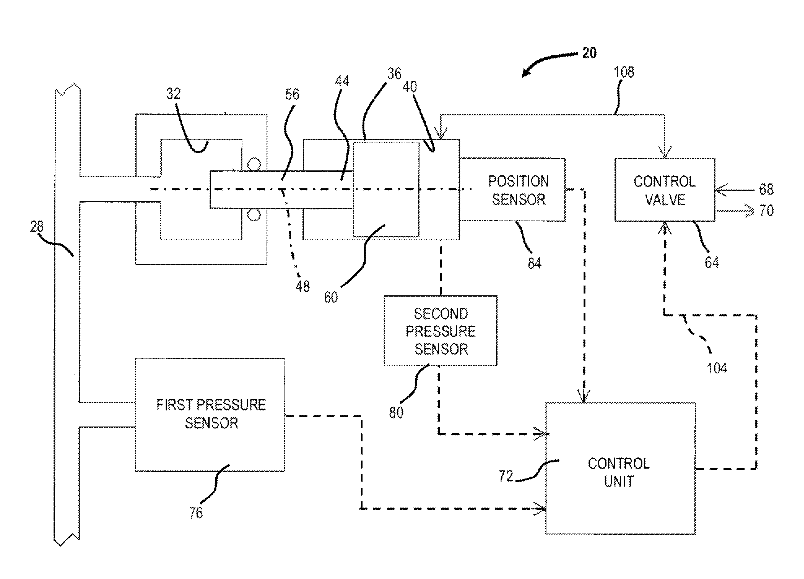
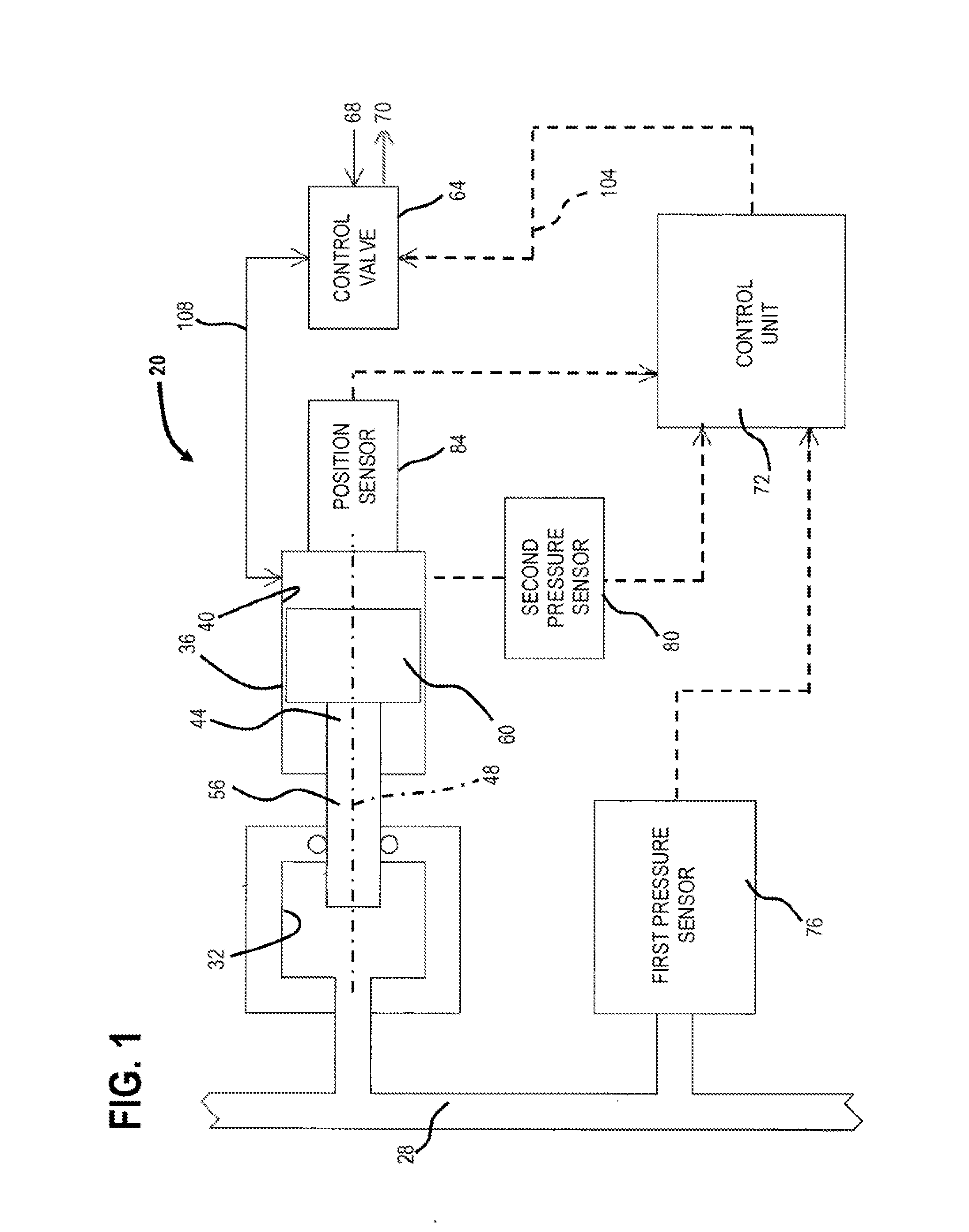
[0013]A dampening system 20 for suppressing pressure fluctuations of a working fluid, such as the one shown in FIG. 1, is fluidly connected to a conduit 28 for conveying a working fluid through, to, or from a hydraulic application (not shown). As shown, the conduit 28 is a pipe; however, the conduit 28 may be otherwise embodied as a tank or any alternative structure which experiences a pressure fluctuation within the working fluid. Working fluids, also known as process fluids, are typically chemical solutions, oils or other petroleum products, water or water based solutions, as well as other non-compressible liquid materials. The working fluid may be a part of various applications (e.g., chemical or petrochemical processing, oil refinement, vehicle braking systems, hydraulic jacks, etc.). Pressure fluctuations often occur in these working fluids due to process variables, pumping inconsistencies, and valve actuation.

[0014]The dampening system 20 includes a control chamber or first ca...


PUM


Abstract

A method is provided for actively compensating for pressure changes of a working fluid within a conduit. A first cavity is provided in fluid communication with the conduit. A second cavity is in fluid communication with a control fluid. A plunger is in communication with both the first cavity and the second cavity and is movable in response to pressure changes of the working fluid in the conduit. The plunger is re-centered. Re-centering the plunger includes the following steps. Position data representative of movement of the plunger is collected. The position data is analyzed with a control unit to determine an average position of the plunger which is offset relative to a center position. The average position of the plunger is compared, with a control unit, to the center position. A signal is relayed from the control unit to a control valve to urge the plunger toward the center position.

Description

BACKGROUND OF THE INVENTION[0001]Hydraulic applications are applications which include movement of a working fluid which is pressurized relative to ambient pressure. These applications include petrochemical or chemical processing, oil refinement, and hydraulically operated implements (e.g., vehicle braking systems, hydraulic jacks, garbage compactors, pneumatic drills, etc.) among others. Working fluids, also known as process fluids, are typically chemical solutions, oils or other petroleum products, water or water based solutions, as well as other liquid materials. In many hydraulic applications, a steady fluid pressure is required to satisfy the needs of the application process. Unwanted pressure fluctuations often occur in these working fluids due to process variables, pumping inconsistencies, and valve actuation.[0002]In known hydraulic applications, such as the ones mentioned above, an accumulator is used to dampen the pressure fluctuations. An accumulator can include a plunger...

Claims


Application Information

Patent Timeline
Patent Type & Authority Applications(United States)
IPC IPC(8): F04B11/00F04B7/02
CPCF04B11/00F04B7/02F16L55/04F15B21/12F15B3/00F16L55/0333F16L55/05F04B11/0058F04B11/0041
Inventor STAVROU, PAUL C.
Owner BOSCH REXROTH AG
Why Eureka
Try Eureka