
Fault detection in rotor driven equipment using rotational invariant transform of sub-sampled 3-axis vibrational data

a technology of vibrational data and rotor drive, which is applied in the direction of machine parts testing, structural/machine measurement, instruments, etc., and can solve problems such as controlling sampling errors

Inactive Publication Date: 2016-08-25
MACHINESENSE LLC
View PDF6 Cites 97 Cited by
  • Summary
  • Abstract
  • Description
  • Claims
  • Application Information

AI Technical Summary

Benefits of technology

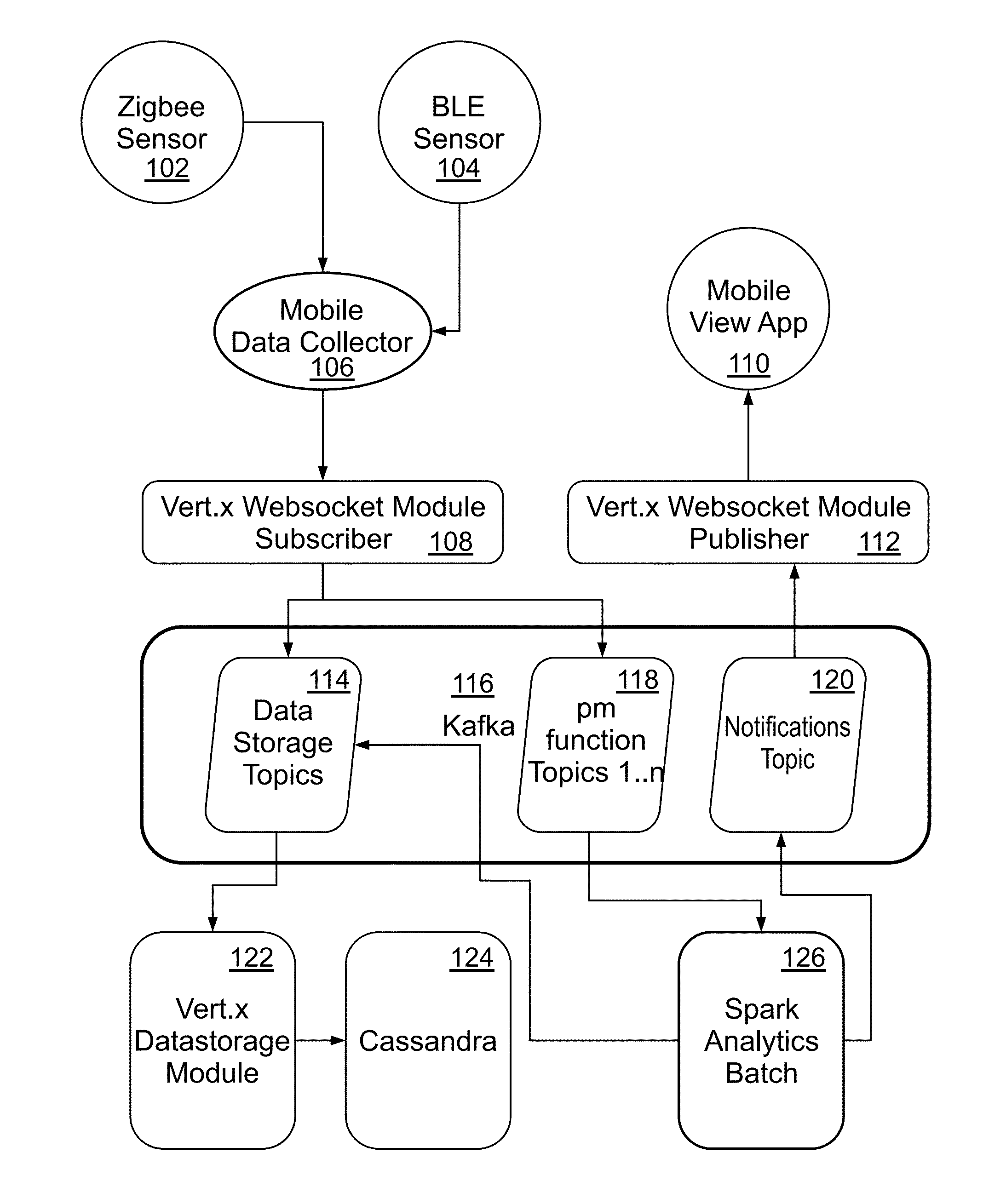
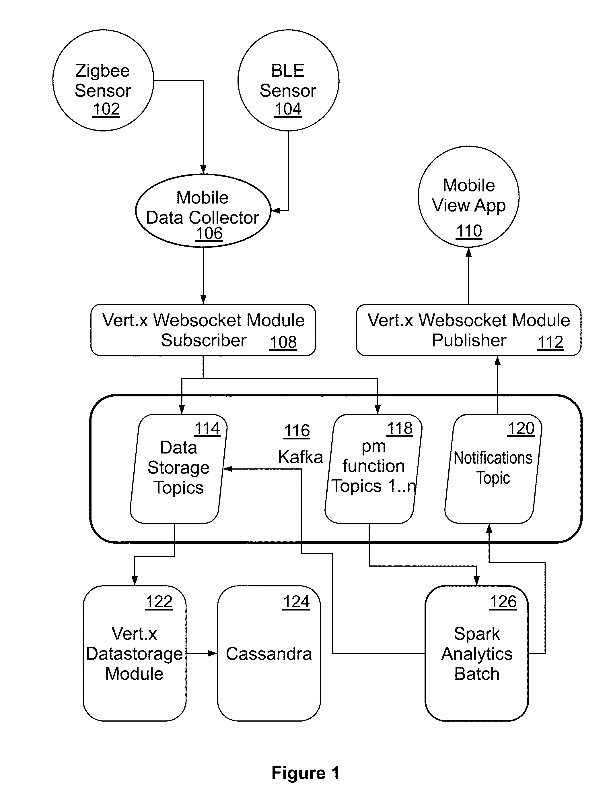
The patent is about a method and system for detecting and predicting blockages and faults in rotor driven equipment using big data analytics. The system includes a mobile device with sensors that collect data from the equipment, which is then transmitted to a big data analytics engine and a machine learning engine. The data is analyzed to identify potential issues with the equipment and alerts are generated when necessary. The technical effects include improved detection and preventive maintenance of rotor driven equipment.

Problems solved by technology

Further, a sampling error may be controlled under a predefined value.

Method used


Image

  • Fault detection in rotor driven equipment using rotational invariant transform of   sub-sampled 3-axis vibrational data
  • Fault detection in rotor driven equipment using rotational invariant transform of   sub-sampled 3-axis vibrational data
  • Fault detection in rotor driven equipment using rotational invariant transform of   sub-sampled 3-axis vibrational data

Examples


Embodiment Construction

[0030]Example embodiments as described below may be used to provide a method, an apparatus and / or a system for fault detection in rotor driven equipment through big data analytics. Although the present embodiments have been described with reference to specific example embodiments, it will be evident that various modifications and changes may be made to these embodiments without departing from the broader spirit and scope of the various embodiments.

[0031]In one or more embodiments, vibrations of a fault free rotor in time domain may be represented by

x_j(t)=Σi=1∞αi*sin(i*Ω*t)|j=1,2,2

Ω is fundamental frequency and i, j, and k are three Cartesian vectors. In vibration analysis of a rotor, revolution per second of rotor may be multiplied by 2π.

[0032]Fundamental harmonics and other harmonics generated by a rotor may depend on the rotor's speed. Rotation speed of the rotor may commonly vary between 200-3000 RPM (Revolutions Per Minute). With such rotation speeds, the fundamental harmonics ...


PUM


Abstract

A method and system of detecting faults in rotor driven equipment includes generating data from one or more vibration sensors communicatively coupled to the rotor driven equipment. The data from the one or more machine wearable sensors is collected onto a mobile data collector. The data is sampled at random to estimate a maximum value. Further, a sampling error may be controlled under a predefined value. The data may be analyzed through a combination of Cartesian to Spherical transformation, statistics of the entity extraction (such as variance of azimuthal angle), big data analytics engine and a machine learning engine. A fault is displayed on a user interface associated with the rotor driven equipment.

Description

FIELD OF TECHNOLOGY[0001]The present invention generally relates to fault detection in rotor equipment. More specifically it relates to fault detection in rotor driven equipment based on a combination of low frequency vibration data, spherical transformation, machine learning and big data architecture.BACKGROUND[0002]Internet of Things (IoT) is a network of uniquely-identifiable, purposed “Things” that are enabled to communicate data pertaining thereto over a wide communication network, whereby the communicated data form a basis for manipulating the operation of the “Things”. The “Thing” in the Internet of Things could virtually be anything that fits into a common purpose thereof. For example, the “Thing” could be a person with a heart rate monitor implant, a farm animal with a biochip transponder, an automobile that has built-in sensors to alert its driver when tire pressure is low, or the like, or any other natural or man-made entity that can be assigned a unique IP address and pr...

Claims


Application Information

Patent Timeline
Patent Type & Authority Applications(United States)
IPC IPC(8): G01H1/00G01M13/04
CPCG01M13/045G01H1/003
Inventor PAL, BIPLABBANSAL, ANSHULDUTTA, SNEHAKARAR, PRATYAYBORAL, SOUMYADEY, ABHISEK
Owner MACHINESENSE LLC
Learn More