Control system for a vehicle

a control system and vehicle technology, applied in the direction of engine-driven generators, road transportation, transportation and packaging, etc., can solve the problems of noise, vibration, harshness, noise, etc., and achieve the effect of preventing damage, high stiffness, and improving the acceleration response of the vehicl

Inactive Publication Date: 2016-09-01
TOYOTA JIDOSHA KK
View PDF0 Cites 11 Cited by
  • Summary
  • Abstract
  • Description
  • Claims
  • Application Information

AI Technical Summary

Benefits of technology

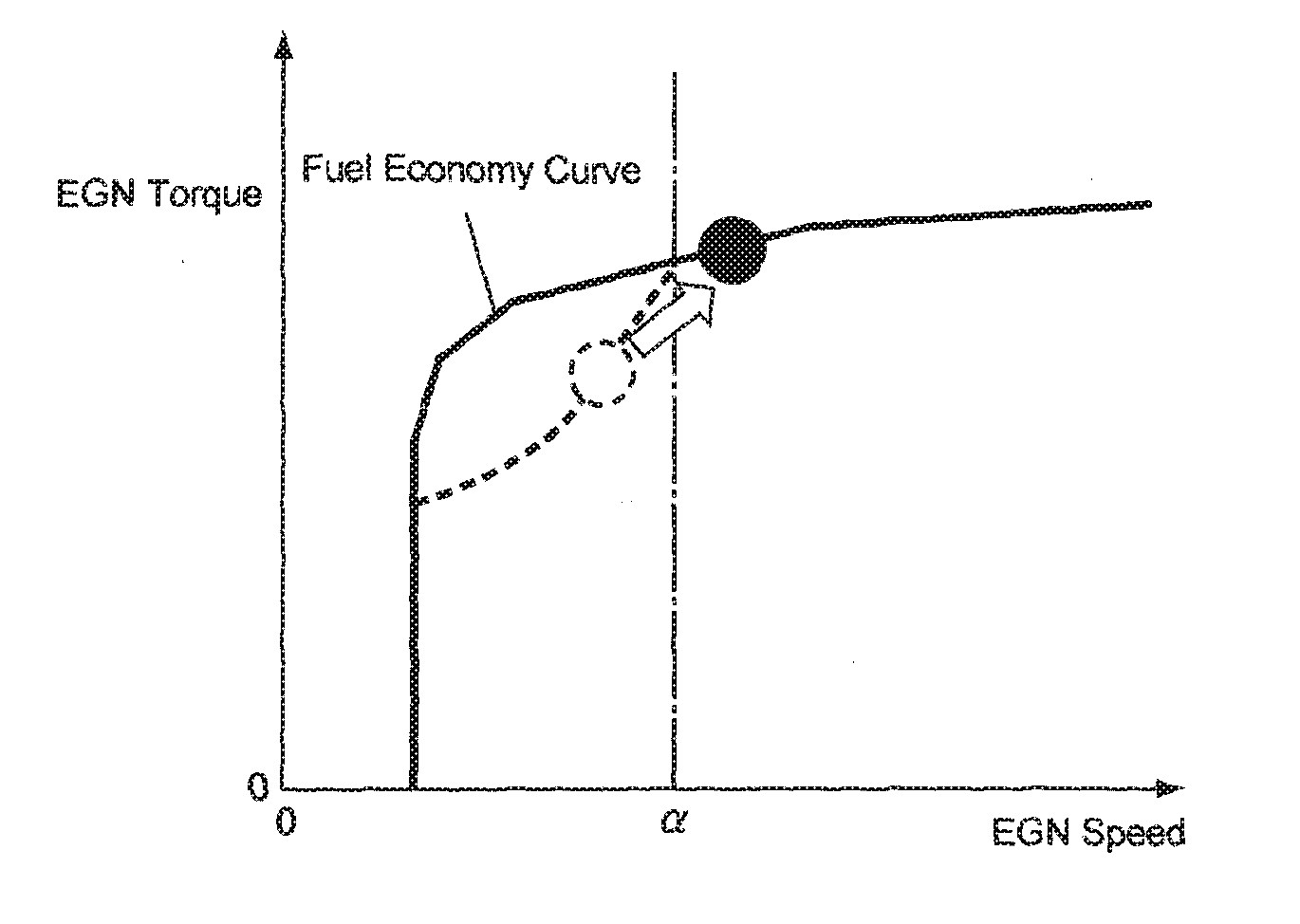
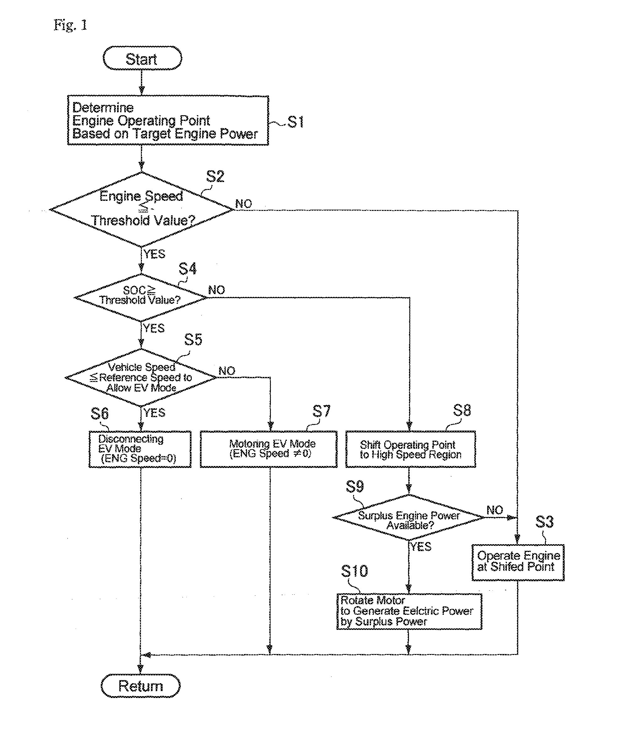
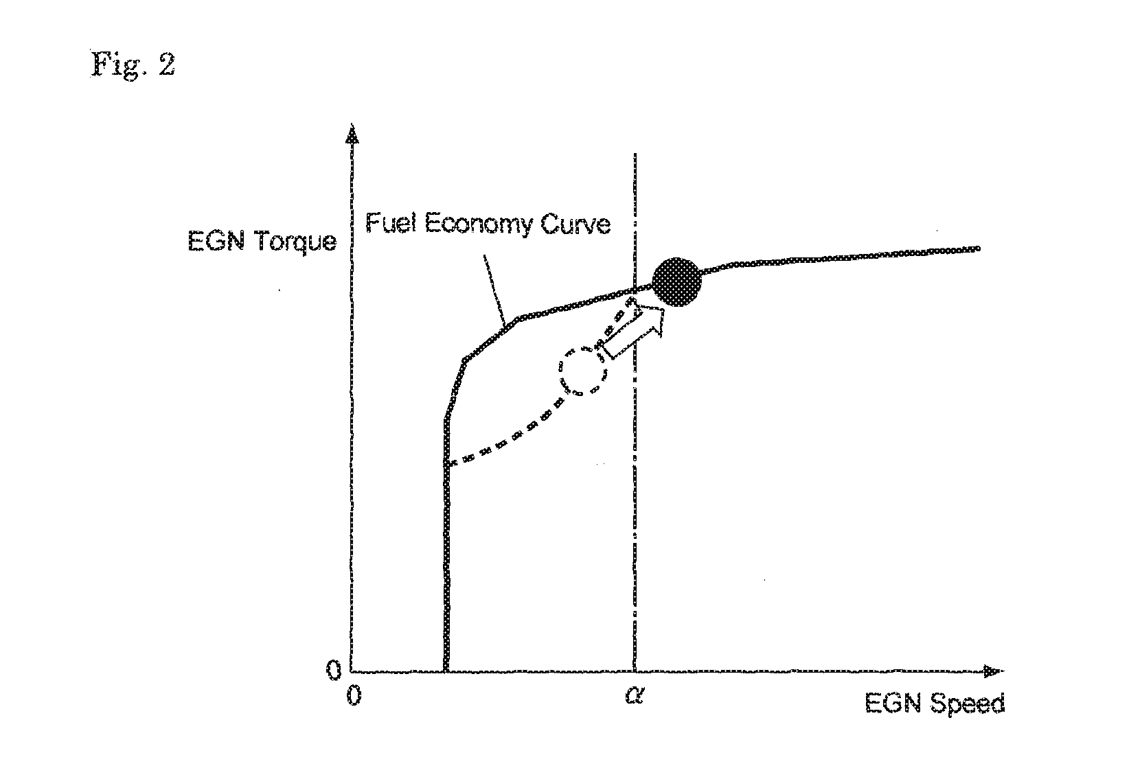
[0004]The present disclosure has been conceived noting the foregoing technical problems, and it is an object of this disclosure to provide a vehicle control system for suppressing torque pulses generated by an engine and resultant vibrations in a vehicle having a clutch adapted to disconnect the engine selectively from a power train.
[0012]Thus, the control system of the present disclosure is configured to determine the target operating point of the engine at which the target engine power based on a required driving force can be generated while achieving a desired fuel economy, and if the target engine speed to be achieved at the determined target operating point is lower than a predetermined threshold value, the vehicle is driven by a torque of the motor. That is, provided that the engine speed is within the low speed region where the torque pulses may appear on the power train, the vehicle is allowed to be driven while disconnecting the engine from the power train and stopping the engine. Therefore, the NVH characteristics of the vehicle will not be deteriorated. To this end, specifically, the clutch is disposed on the power train, and the engine is disconnected from the power train by disengaging the clutch when the engine speed is lower than the threshold value. In addition, the clutch is adapted to be engaged while causing a slip so that an engagement shock will not be caused. Therefore, a spring having high stiffness may be used in a torsional damper for damping the vibrations of the power train. Consequently, an acceleration response of the vehicle can be improved.
[0013]As described, in the vehicle to which the control system of the present disclosure is applied, the first motor is connected with the first rotary element, the engine is connected with the second rotary element through the clutch, and the second motor is connected with the third rotary element. Provided that the vehicle is driven by the second motor while disengaging the clutch, and that the vehicle speed exceeds the predetermined speed, the clutch is engaged and the engine is rotated by the first motor. In this situation, specifically, the clutch is engaged while lowering the rotational speed of the second rotary element to zero by the first motor. Thus, the rotational speed of the second rotary element will not be raised excessively when engaging the clutch so that the power distribution is prevented from being damaged. In addition, since the engine has already been rotated by the first motor, the rotational speed of the engine can be raised smoothly to start the engine by the first motor when the driving mode is shifted to drive the vehicle by the engine. Further, the current to be applied to the first motor can be reduced.
[0014]As also described, the control system of the present disclosure is configured to drive the engine at another target operating point at which the target engine speed is higher than the threshold value, if the target engine speed to be achieved at the former target operating point of the engine is lower than the threshold value, and a state of charge of the electric storage device is smaller than a predetermined threshold value. In this case, the engine is connected with the powertrain by engaging the clutch, and if the engine is allowed to generate the power higher than the required power to drive the vehicle, the first motor is rotated by the surplus power of the engine to generate the electric power. Therefore, the electric storage device is allowed to be charged efficiently utilizing the surplus power of the engine.

Problems solved by technology

In this case, torque pulses and resultant shocks may be worsened, that is, NVH (i.e., noise, vibrations and harshness) characteristics may be deteriorated.

Method used


Image

  • Control system for a vehicle
  • Control system for a vehicle
  • Control system for a vehicle

Examples


Embodiment Construction

[0020]The vehicle control system of the present disclosure is applied to a vehicle having a clutch for selectively disconnecting the engine from the power train. For this purpose, the clutch is adapted to be engaged gradually while changing a torque transmitting capacity thereof.

[0021]An example of a power train of the vehicle to which the present disclosure is applied is illustrated in FIG. 3. In the vehicle shown in FIG. 3, the power of the engine (ENG) 1 is partially transmitted to the driving wheels 2 by a mechanical means. The remaining power of the engine 1 is once converted into an electric power, and then converted into a mechanical power again to be transmitted to the driving wheels 2. In order to distribute the power of the engine 1, a power distribution device 3 is disposed on the power train 10. As the conventional two-motor type hybrid drive units, a single-pinion type planetary gear unit adapted to perform a differential action among three rotary elements is used as th...


PUM


Abstract

A control system for a vehicle having an engine and a motor configured to reduce torque pulses and vibrations. The control system is comprised of a determining means that determines a target operating point of the engine at which a target engine power based on a required driving force is generated while improving fuel economy (step S1); and an electric vehicle mode setting means that shift a driving mode to the EV mode to drive the vehicle by the motor, if a target engine speed to be achieved at the target operating point determined by the determining means is lower than a predetermined threshold value (steps S2, S6).

Description

TECHNICAL FIELD[0001]This disclosure relates to a control system for a vehicle having a clutch adapted to gradually change torque transmitting capacity thereof and to selectively disconnect an engine from a power train.BACKGROUND ART[0002]An example of the vehicle of this kind is disclosed in Japanese Patent Laid-Open No. 08-295140. According to the teachings of Japanese Patent Laid-Open No. 08-295140, the first gear element of the differential gear unit is coupled to the generator, the second gear element is coupled to the motor to serves as the output element, and the third gear element is coupled to the breaking means. The third gear element is also coupled to the engine via the clutch. Provided that an opening degree of the accelerator is larger than 80% and a vehicle speed is lower than 30 km / h, the engine is disconnected from the third gear element, and the vehicle is driven by powers of the motor and the generator.[0003]Thus, according to the teachings of Japanese Patent Laid...

Claims


Application Information

Patent Timeline
Patent Type & Authority Applications(United States)
IPC IPC(8): B60W20/10B60K6/445B60K6/387B60W20/40B60W30/188B60L50/16
CPCB60W20/10B60W20/40B60W30/1882B60W2710/0644B60K6/445B60W2030/206B60W2510/0638B60K6/387B60K6/365B60W10/02B60W10/06B60W10/08B60W10/26B60W20/16Y02T10/84Y02T10/40Y02T10/62Y02T10/60
Inventor HATA, KENSEIIWASE, YUJISUZUKI, YOSUKEKATO, KOICHIKITABATAKE, HIROTATSUNOBUYASU, SEITAROMOTEKI, TARO
Owner TOYOTA JIDOSHA KK
Why Eureka
Try Eureka