Method for controlling mixer, controller and mixer

a technology of controller and mixer, which is applied in the field of living electrical devices, can solve the problems of reduced high level of heat released by the motor in the existing mixer, and easy damage to the internal coil of the motor, so as to avoid the influence of the service life of the fan, avoid the damage of the internal coil, and enhance the service life of the motor

Active Publication Date: 2016-09-08
FOSHAN CITY SHUNDE JUTIAN ELECTRIC APPLIANCE
View PDF2 Cites 3 Cited by
  • Summary
  • Abstract
  • Description
  • Claims
  • Application Information

AI Technical Summary

Benefits of technology

[0049]1. The operation of the fan is stopped later than the motor, so as to release the residual heat out of the motor, thereby avoiding the damage of the internal coils within the motor due to the residual heat and enhancing the service life of the motor.
[0050]2. The vibration and the noise caused by the synchronous rotation of the fan and the motor and the issues causing that the fan is worn down in an expedited way and that the service life of the fan is influenced are avoided. The fan of the present invention produces a noise ranging from 65 to 85 db when it is working, as compared to the noise up to 85 to 100 db produced by the conventional controlling structure in which the fan and the motor synchronously operate. The fan of the present invention has the features of low working noise and long service life.

Problems solved by technology

The motors in the existing mixers release high level of heat when the mixers are working, due to high rotation speed of the motors.
1. The operation of the fan and the motor will be stopped at the same time, while the internal temperature of the motor is still very high at this time. Thus, the internal coils of the motor will be easily damaged, and the service life of the motor will be reduced.
2. The fan is synchronously rotated with the motor at the same speed as the motor. When the motor is rotated at high speed, the vibration and the high level of noise up to 85 to 100 db will be generated in the fan, and thus the fan will be worn down in an expedited way, thereby producing an influence on the service life of the fan and reducing the performance of the product.

Method used


Image

  • Method for controlling mixer, controller and mixer
  • Method for controlling mixer, controller and mixer
  • Method for controlling mixer, controller and mixer

Examples


Embodiment Construction

[0060]The technical solution in the working examples of the present invention will be clearly and completely described as below, by referring the drawings of the present invention. It should be understood that the working examples described below are only a part of the working examples of the present invention, rather than all of the working examples. Other working examples obviously obtained by the ordinary skilled in the art come within the protection scope of the present invention.

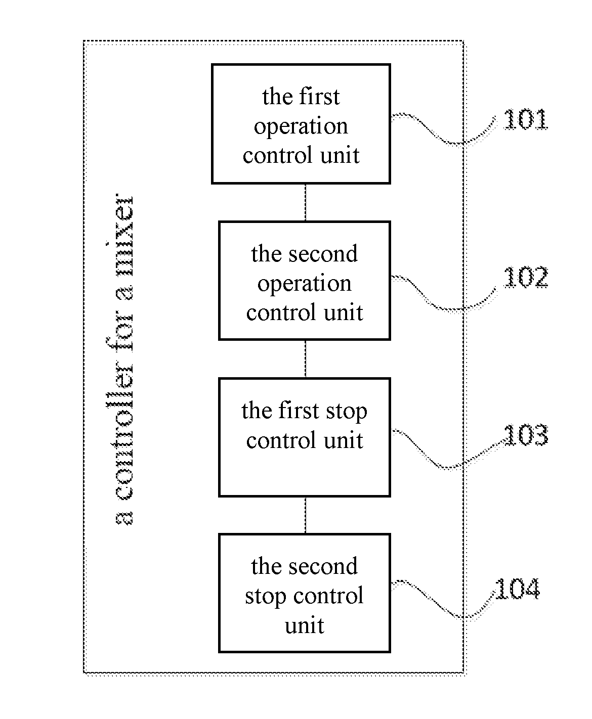
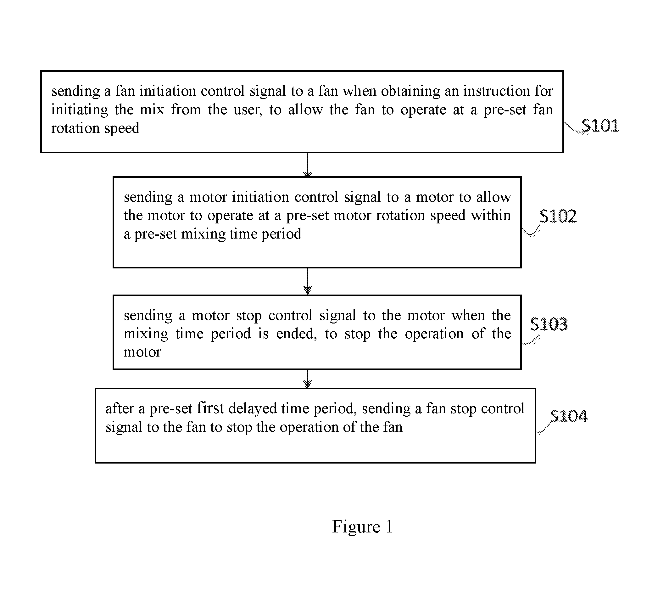
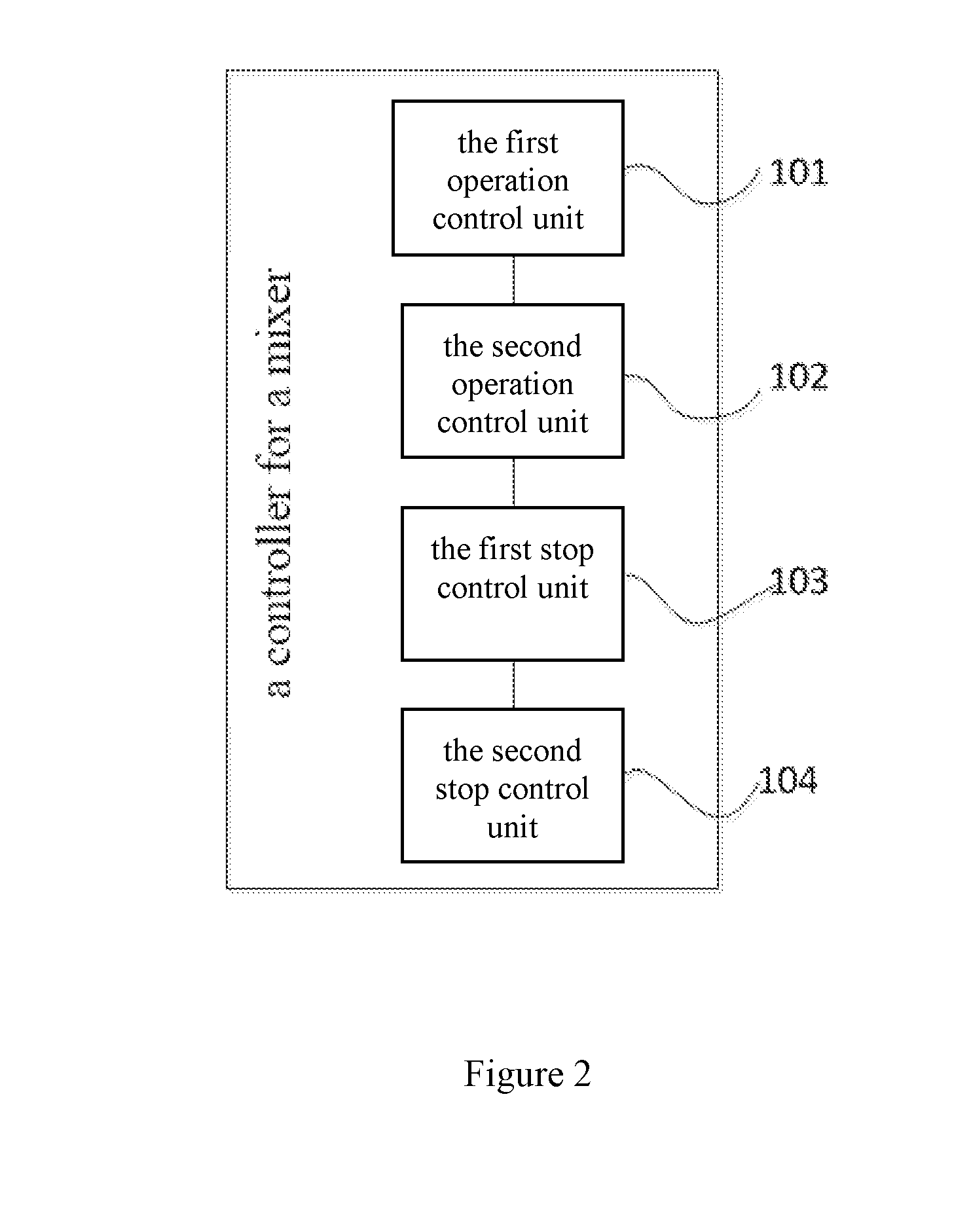
[0061]Referring to FIG. 1, a schematic flow diagram of the first working example of the method for controlling the mixer of the present invention is provided, wherein the mixer includes a housing, a cup body disposed on the housing, a motor and a fan disposed within the housing, and a mixing part disposed within the cup body and co-axially connected to the motor, and wherein the fan and the motor are opposite to each other, the method for controlling the mixer includes:

[0062]S101, sending a fan initiati...


PUM


Abstract

The present invention discloses a method for controlling a mixer, including sending a fan initiation control signal to the fan when obtaining a instruction for initiating the mix from the user, to allow the fan to operate at a pre-set fan rotation speed; sending a motor initiation control signal to the motor to allow the motor to operate at a pre-set motor rotation speed within a set mixing time period; wherein the instruction for initiating the mix includes the mixing time period; sending a motor stop control signal to the motor when the mixing time period is ended to stop the operation of the motor; and sending a fan stop control signal to the fan after a pre-set first delayed time period to stop the operation of the fan. Meanwhile the present invention also provides a controller for a mixer and a mixer.

Description

CROSS-REFERENCE TO PRIOR APPLICATION[0001]This application claims the benefit of Chinese Patent Application No. 201510097885.6, filed on Mar. 5, 2015, Chinese Patent Application No. 201520127769.X, filed on Mar. 5, 2015, Chinese Patent Application No. 201520476513.X, filed on Jul. 2, 2015, and Chinese Patent Application No. 201510916053.2, filed on Dec. 11, 2015, which are incorporated herein by reference.FIELD OF THE INVENTION[0002]The present invention relates to the field of living electrical devices, and particularly, to a method for controlling a mixer, a controller and a mixer.BACKGROUND OF THE INVENTION[0003]In our lives, mixers such as soymilk makers, coffee machines, sand ice makers and the like, which are commonly used as home electrical appliances, are extensively used to mix and smash various food, so as to make increasing delicious food in various styles.[0004]The motors in the existing mixers release high level of heat when the mixers are working, due to high rotation ...

Claims


Application Information

Patent Timeline
Patent Type & Authority Applications(United States)
IPC IPC(8): A47J43/08A47J43/046
CPCA47J43/046A47J43/085A47J43/0716
Inventor LE, MEIYI
Owner FOSHAN CITY SHUNDE JUTIAN ELECTRIC APPLIANCE
Why Eureka
Try Eureka