Catheter Detection, Tracking And Virtual Image Reconstruction

a catheter and imaging technology, applied in the field of medical imaging, can solve the problems of difficult image of the catheter tip with the dark background image of the radiodense, patient morbidity,

Active Publication Date: 2016-09-08
UNIVERSITY OF ROCHESTER
View PDF0 Cites 6 Cited by
  • Summary
  • Abstract
  • Description
  • Claims
  • Application Information

AI Technical Summary

Problems solved by technology

During various angiographic procedures, such as embolization, where a radiodense coil mass is extruded into an aneurysm by way of a catheter, it becomes difficult to image the tip of the catheter with the dark background image of the radiodense coil mass that is being deployed into the aneurysm.
Any ambiguities in the position and movement of the catheter tip during procedures such as embolization or stenting represents the potential for error and resulting patient morbidity.

Method used


Image

  • Catheter Detection, Tracking And Virtual Image Reconstruction
  • Catheter Detection, Tracking And Virtual Image Reconstruction
  • Catheter Detection, Tracking And Virtual Image Reconstruction

Examples


second embodiment

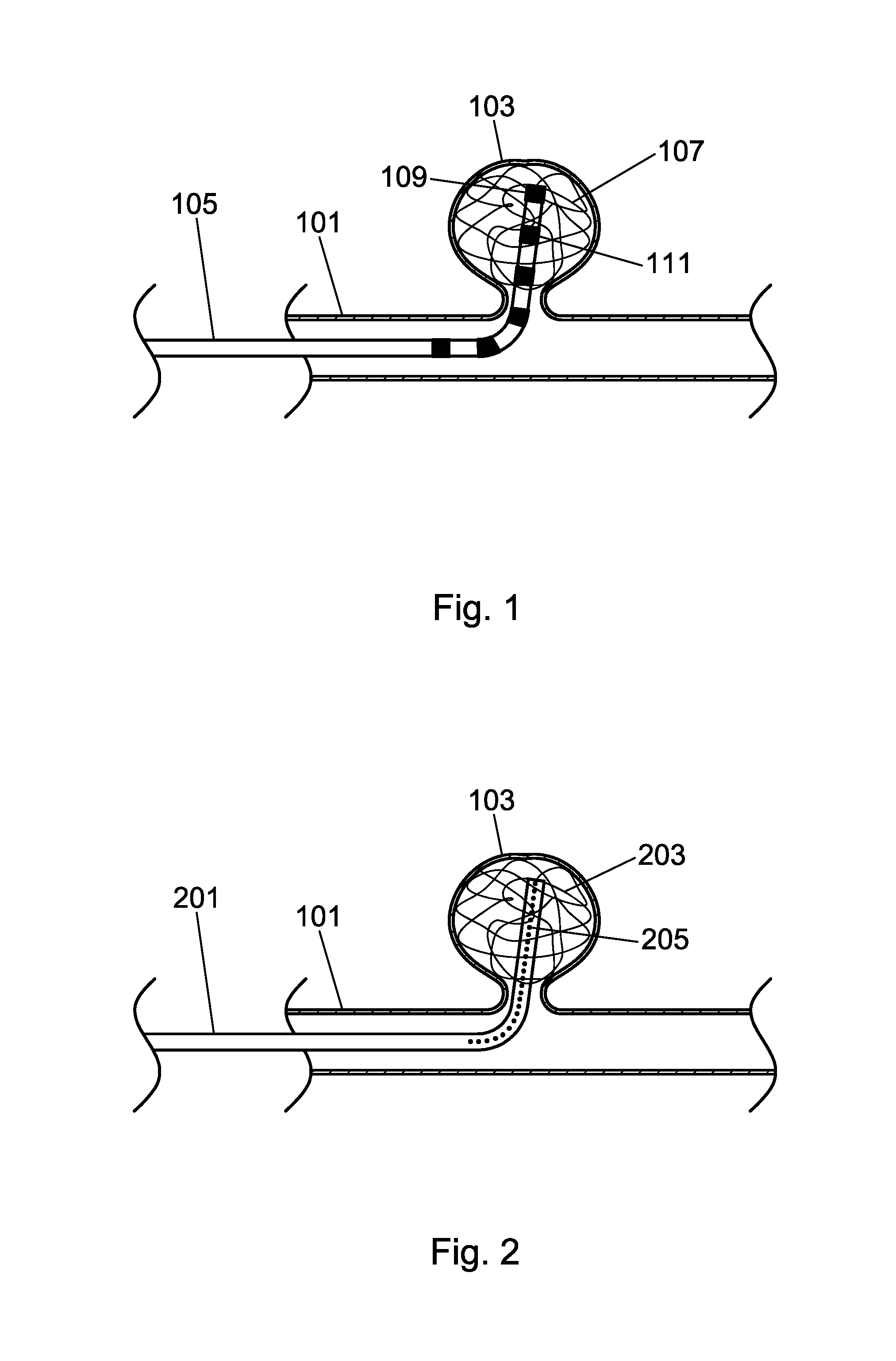
[0028]Turning to the drawings, FIGS. 1-3 depict several embodiments of the catheter of the present invention in use placing a coil in an aneurysm. FIG. 1 depicts a vessel 101 such as an artery with an aneurysm 103 formed as a bulging, weak area in the wall of the artery 101. A minimally invasive technique to treat the aneurysm is endovascular coiling, where a soft, flexible wire known as a coil 107 is fed into the aneurysm by way of a catheter 105. The coil 107 is commonly made from a metal such as platinum. The coil 107 creates a twisted mass that fills the space within the aneurysm and causes clotting that seals off the aneurysm from the artery. During endovascular coiling, the surgeon moves the catheter 105 into the aneurysm 103 in such a way as to allow filling of the aneurysm space with the coil 107 without contacting or piercing the wall of the aneurysm, an event that could cause patient morbidity. The catheter is placed in a small incision in the groin area of a patient and u...

third embodiment

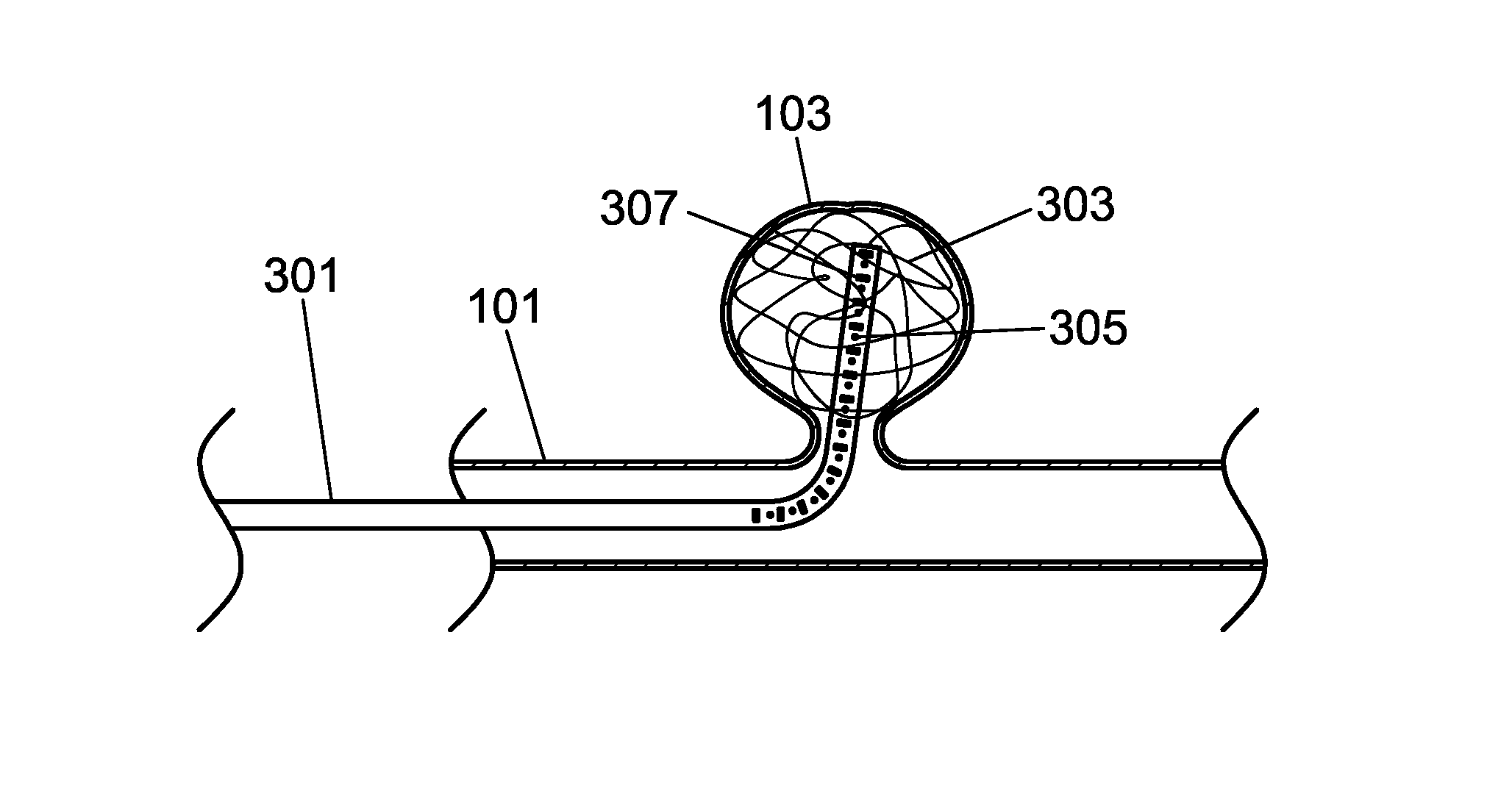
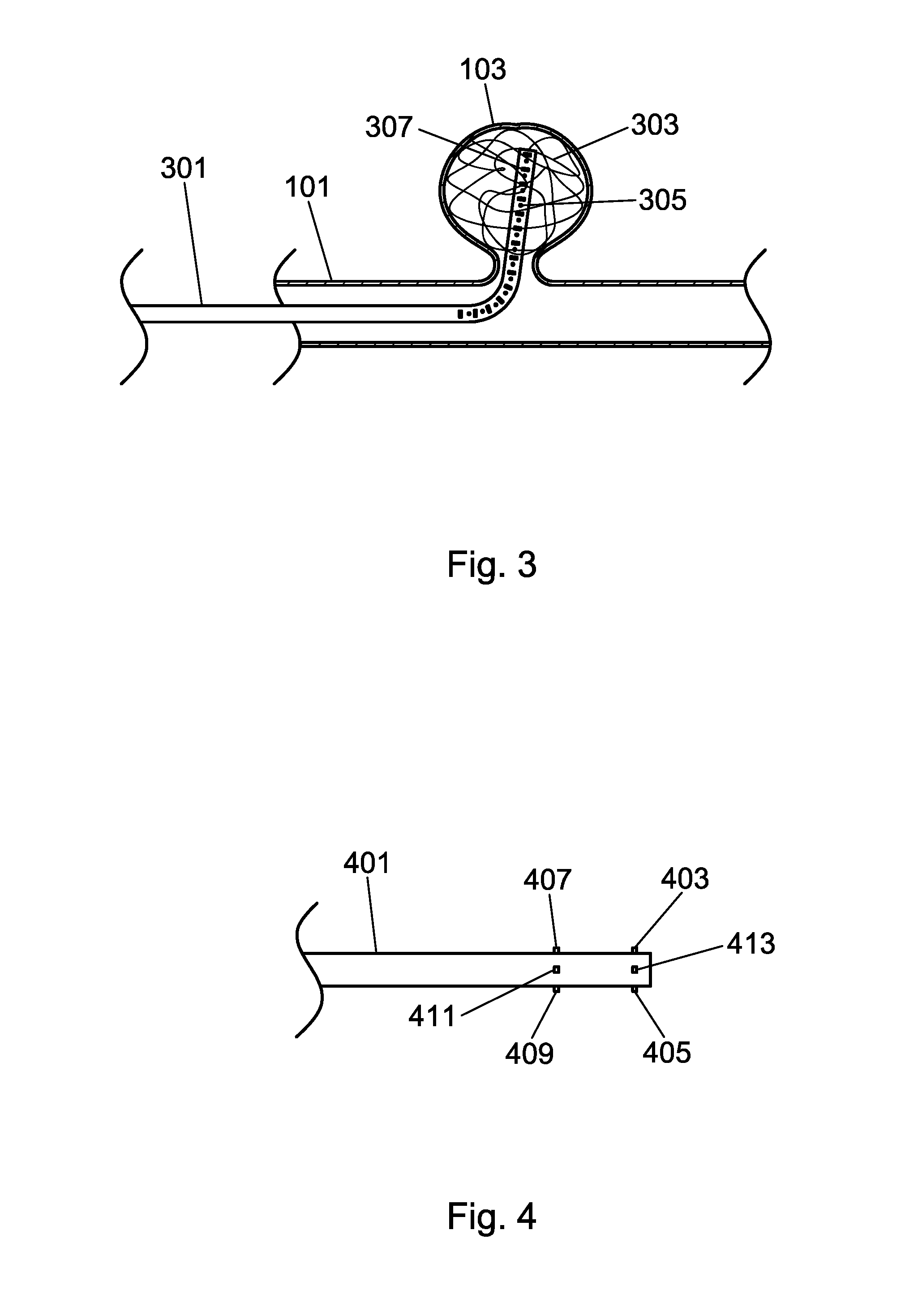
[0029]FIG. 3 depicts the present invention where the catheter 301 comprises a first marker 305 and a second marker 307, where the markers provide a fluoroscopic representation of the tip of the catheter, trajectory, and overall shape. The first marker 305 and the second marker 307 are made from a radiodense material such as a metal, or an emitter of electromagnetic radiation such as quantum dots, and provide a fluoroscopic representation of the catheter 301 and tip without being obscured by the coil 303. The first marker 305 and the second marker 307 are of differing geometries to provide additional information to the imaging system regarding catheter location. In some embodiments of the present invention, different marker geometries are employed to provide additional information to an imaging system and related computer system regarding catheter location during a medical procedure. This information may include, for example, a linear coordinate along the insertion / extraction axis, a...


PUM


Abstract

A catheter and related X-ray imaging system for detection, tracking, and virtual image reconstruction is disclosed. The catheter and imaging system allow for the visualization of the catheter or a part of the catheter such as the tip during procedures that would otherwise obscure the catheter or part of the catheter from view. An example of such a procedure is the deployment of a coil in an aneurysm where the radiodense nature of many coil materials would otherwise make detection and tracking of the catheter tip difficult or impossible. The catheter has detectable markers that provide information to an imaging system regarding the coordinates of the catheter or catheter tip and the direction of the catheter tip during clinical procedures.

Description

CROSS REFERENCE TO RELATED PATENT APPLICATIONS[0001]This application claims priority to U.S. Patent Application Ser. No. 62 / 129,254 filed Mar. 6, 2015 entitled “Catheter Detection, Tracking And Virtual Image Reconstruction” by Jonathan Jay Stone and Brenton Joseph LaRiccia, the entire disclosure of which is incorporated herein by reference.BACKGROUND OF THE INVENTION[0002]1. Field of the Invention[0003]The present invention relates generally to medical imaging, and more particularly to catheter detection tracking, and virtual image reconstruction.[0004]2. Description of the Related Art[0005]During various angiographic procedures, such as embolization, where a radiodense coil mass is extruded into an aneurysm by way of a catheter, it becomes difficult to image the tip of the catheter with the dark background image of the radiodense coil mass that is being deployed into the aneurysm. The correct movement and placement of the catheter during embolization is critical for not only optima...

Claims


Application Information

Patent Timeline
Patent Type & Authority Applications(United States)
IPC IPC(8): A61B6/12A61M25/01A61B6/00
CPCA61B6/12A61B6/485A61B6/501A61M25/0108A61B6/5205A61B17/12113A61B17/1214A61B2017/1205A61B2090/067A61B2090/364A61B2090/376A61B90/94A61B2090/3966A61B2034/2051A61B2034/2048
Inventor STONE, JONATHAN JAYLARICCIA, BRENTON JOSEPH
Owner UNIVERSITY OF ROCHESTER
Why Eureka
Try Eureka