Light Bulb

Active Publication Date: 2016-09-08
BUSTER & PUNCH LTD
View PDF19 Cites 10 Cited by
  • Summary
  • Abstract
  • Description
  • Claims
  • Application Information

AI Technical Summary

Benefits of technology

[0030]In a further embodiment, a light source is provided substantially along the centre of the light pipe. This may be preferable as it may provide a more even spread of light from the light bulb if the light pipe has an extended length.
[0031]In another preferred embodiment the coloured lines may include a photo luminescent material. The inclusion of a photo luminescent material in the coloured lines may be preferred as it provides an additional means of manipulating the light output of the light bulb, including the production of light when the bulb is off.

Problems solved by technology

Furthermore, the length of the light pipe may be used to carry light into an otherwise difficult to illuminate, long, thin bulb with a single point light source.

Method used


Image

  • Light Bulb
  • Light Bulb
  • Light Bulb

Examples


Embodiment Construction

[0040]The invention will now be described by way of example with reference to the following figures in which:

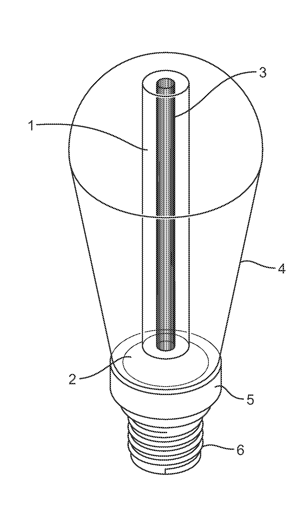
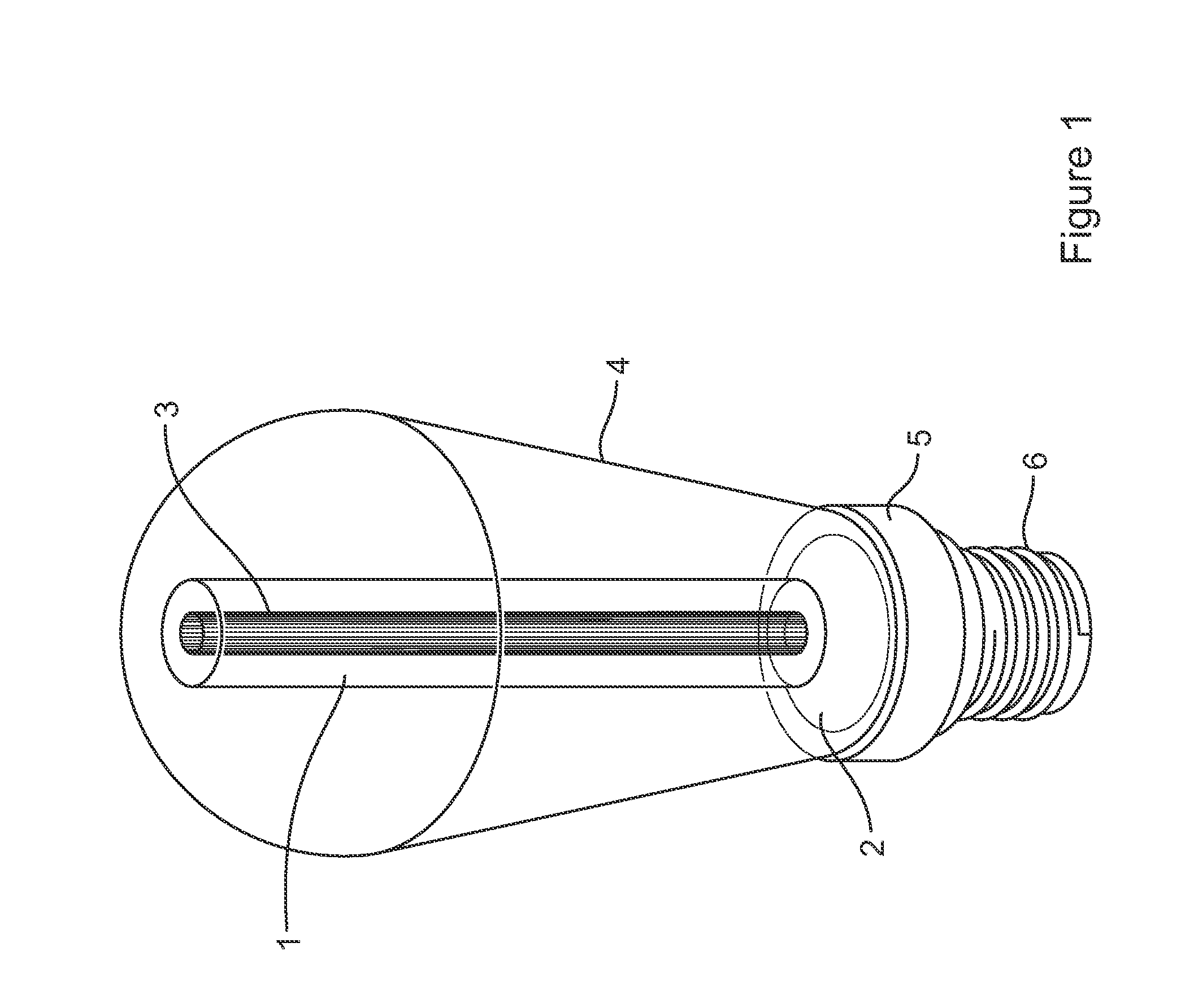
[0041]FIG. 1 is a schematic view of a light bulb;

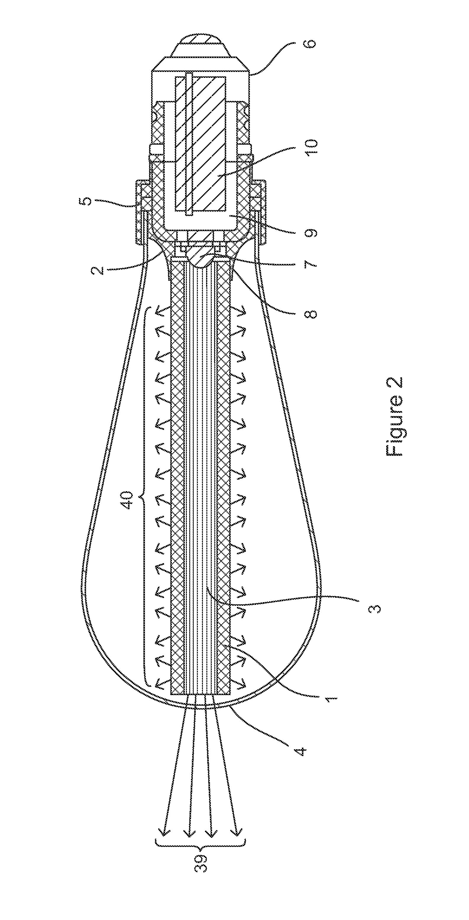
[0042]FIG. 2 is a schematic view of a cross section of a light bulb;

[0043]FIG. 3 is a schematic of a process of extruding the light pipe;

[0044]FIG. 4 is a schematic focusing on the inclusion of the coloured lines in the extruded light pipe;

[0045]FIG. 5 is a schematic view of a light bulb with a triangular cross section;

[0046]FIG. 6 is a schematic view of a light bulb with a rectangular cross section;

[0047]FIG. 7 is a schematic view of a light bulb where the coloured lines extend helically within the light pipe;

[0048]FIG. 8 is a schematic view of four different embodiments of a glass bulb that may be added to the light bulb; and

[0049]FIG. 9 is a schematic view of a light bulb with a translucent or frosted light pipe.

[0050]Referring to the drawings in detail, FIG. 1 depicts an embodiment of the light bulb wherein a light pipe 1 w...


PUM


Abstract

A light bulb, in particular one which has a light pipe in the form of a bar or tube, mounted to a light source. The light pipe has coloured lines extending along and within it. When illuminated by the light source, the light pipe acts as a means for dissipating light, providing the desirable effect of a traditional filament or incandescent bulb without the high temperatures and low energy efficiency associated with such a light source. Such a light bulb may also include a screw or bayonet fitting, allowing it to be retrofitted into existing lighting units, providing backwards compatibility with existing lighting installations.

Description

FIELD OF THE INVENTION[0001]This invention relates to a light bulb.BACKGROUND TO THE INVENTION[0002]The need to reduce energy consumption is a universal consideration when supplying electrical goods to consumers. Due to their prevalence throughout society, light bulbs account for a large percentage of today's energy usage and thus much effort has been focused on the development of energy efficient lightbulbs. However, current energy efficient bulbs are not a complete solution to the replacement of the traditional filament or incandescent light bulb.[0003]Fluorescent ‘energy saving’ bulbs are commonly used to replace traditional filament style bulbs, although this is frequently with complaint. Commonly cited problems include a lengthy period after such a bulb is turned on before it reaches its full brightness, and a general dimness of the bulbs compared to their filament based predecessors. Other alternatives include halogen lights and light emitting diodes (LEDs). Whilst these sourc...

Claims


Application Information

Patent Timeline
Patent Type & Authority Applications(United States)
IPC IPC(8): F21K99/00F21V8/00
CPCF21K9/135G02B6/0008G02B6/0003G02B6/0006G02B6/001F21V5/00F21V7/00F21V31/005F21K9/232F21K9/61F21Y2115/10Y02B20/30B29D11/00663F21V99/00F21V2200/00
Inventor DULLEY, IAINMINALE, MASSIMO
Owner BUSTER & PUNCH LTD
Why Eureka
Try Eureka