Electro-wetting display panel and electro-wetting display apparatus
a display panel and display technology, applied in the field of display technology, can solve the problems of degrading display quality, poor performance of conventional electro-wetting display gray-scale, etc., and achieve the effect of preventing the hysteresis phenomenon of oil layer (non-polarized liquid)
- Summary
- Abstract
- Description
- Claims
- Application Information
AI Technical Summary
Benefits of technology
Problems solved by technology
Method used
Image
Examples
first embodiment
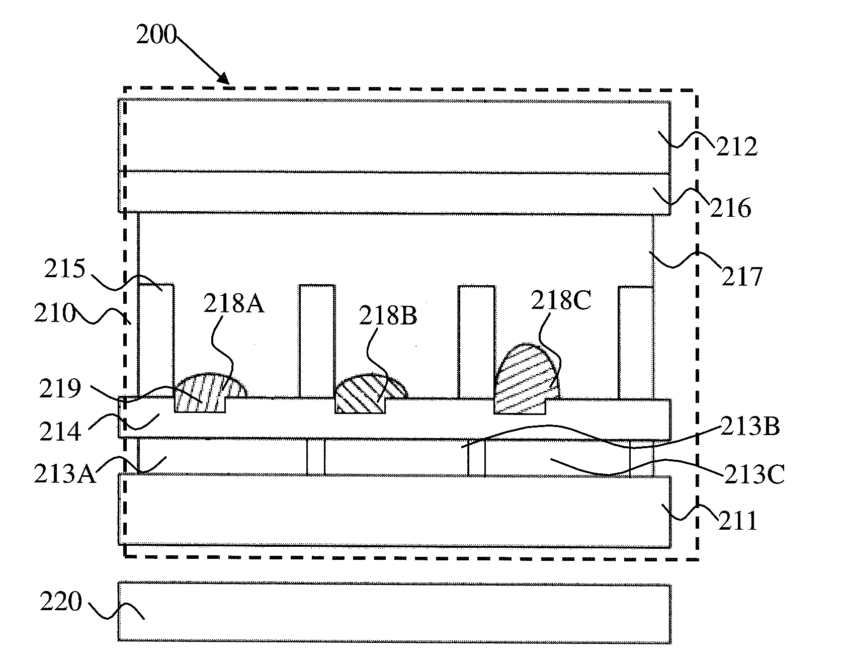
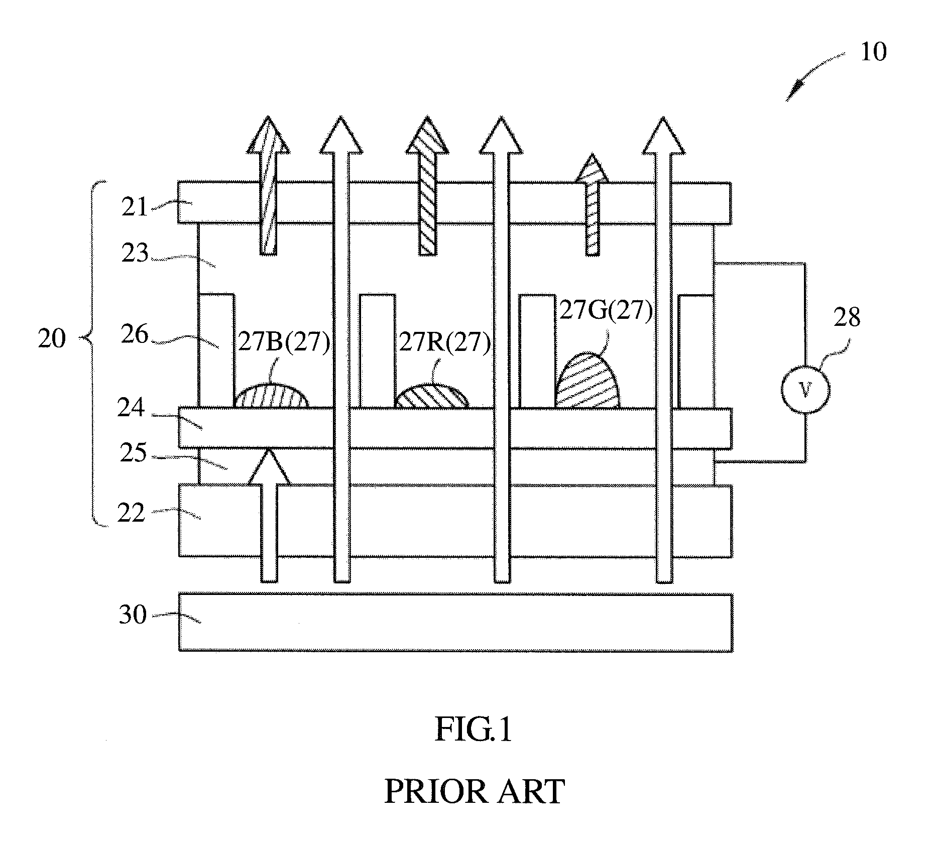
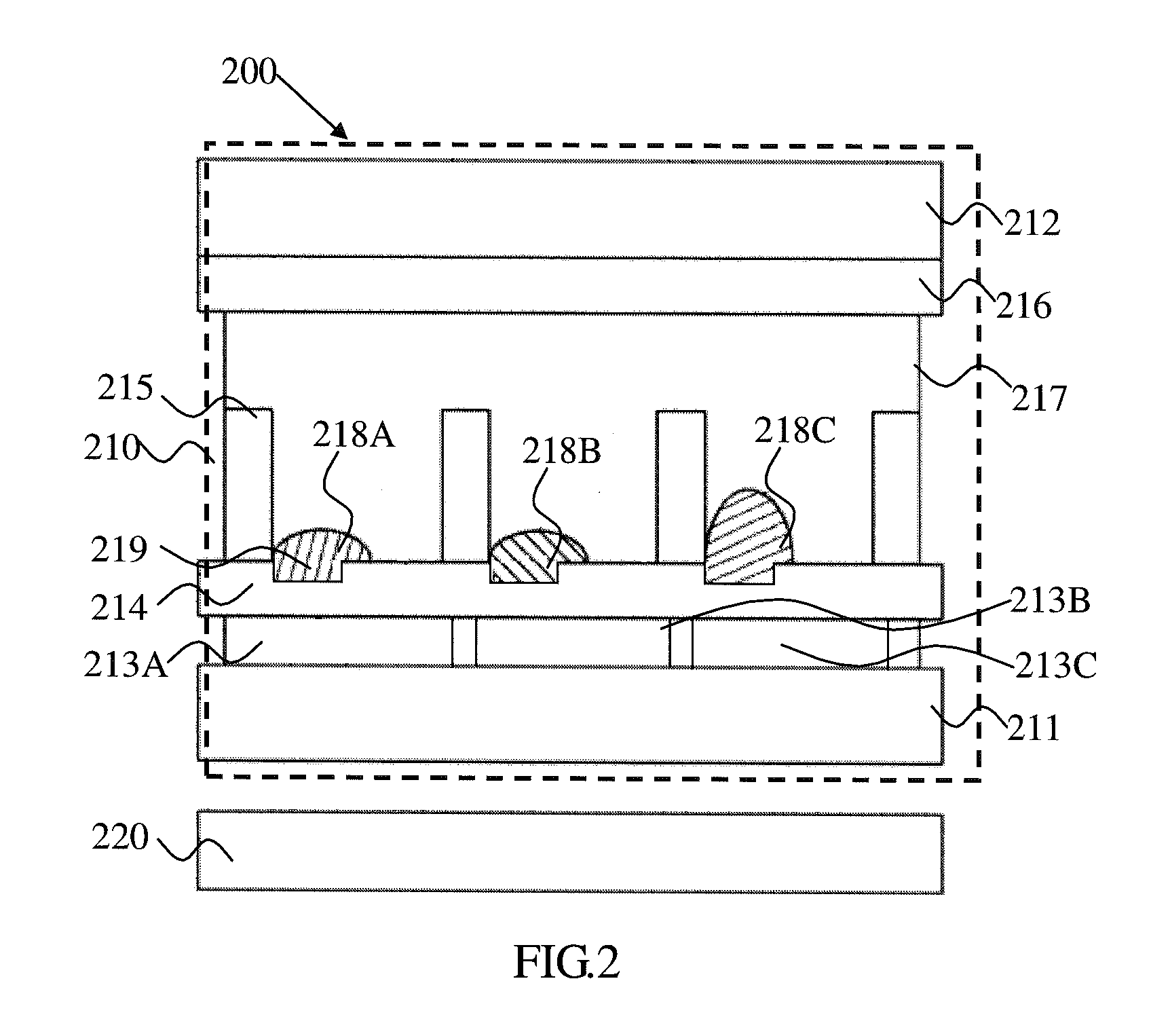
[0030]FIG. 2 is a schematic diagram showing an electro-wetting display apparatus according to the present invention. The electro-wetting display apparatus 200 of the present embodiment comprises an electro-wetting display panel 210 and a light source module 220. The light source module 220 is configured to emit light rays. The electro-wetting display panel 210 comprises a first transparent substrate 211, a second transparent substrate 212, and pixel units. The first transparent substrate 211 and the second transparent substrate 212 are disposed opposite to each other.
[0031]The pixel units comprise first electrodes 213A, 213B, and 213C, a first hydrophobic layer 214, a plurality of first barriers 215, a second electrode 216, a polarized liquid 217 and a plurality of first non-polarized liquids 218A, 218B, and 218C. The first electrodes 213 are disposed in pixel areas of the first transparent substrate 211, and the first hydrophobic layer 214 is disposed on the first electrodes 213. T...
second embodiment
[0038]FIG. 3 is a schematic diagram showing an electro-wetting display apparatus according to the present invention. The electro-wetting display apparatus 300 of the present embodiment comprises an electro-wetting display panel 310 and a light source module 320. The light source module 320 is configured to emit light rays. The electro-wetting display panel 310 comprises a first transparent substrate 311, a second transparent substrate 312, and pixel units. The first transparent substrate 311 and the second transparent substrate 312 are disposed opposite to each other.
[0039]The pixel units comprise first electrodes 313A, 313B, and 313C, a first hydrophobic layer 314, a plurality of first barriers 315, second electrodes 316A, 316B, and 316C, a polarized liquid 317, and a plurality of first non-polarized liquids 318A, 318B, and 318C, a second hydrophobic layer 319, a plurality of second barriers 321, and a plurality of second non-polarized liquids 322A, 322B, and 322C.
[0040]The first e...
third embodiment
[0048]FIG. 4 is a schematic diagram showing an electro-wetting display apparatus according to the present invention. The electro-wetting display apparatus 400 of the present embodiment comprises an electro-wetting display panel 410 and a light source module 420. The light source module 420 is configured to emit light rays. The electro-wetting display panel 410 comprises a first transparent substrate 411, a second transparent substrate 412, and pixel units. The first transparent substrate 411 and the second transparent substrate 412 are disposed opposite to each other.
[0049]The pixel units comprise first electrodes 413A, 413B, and 413C, a first hydrophobic layer 414, a plurality of first barriers 415, a second electrode416, a polarized liquid 417 and a plurality of first non-polarized liquids 418A, 418B, and 418C. The first electrodes 413 are disposed in pixel areas of the first transparent substrate 411, and the first hydrophobic layer 414 is disposed on the first electrodes 413. Th...
PUM
 Abstract
Description
Claims
Application Information
 - R&D
- Intellectual Property
- Life Sciences
- Materials
- Tech Scout
- Unparalleled Data Quality
- Higher Quality Content
- 60% Fewer Hallucinations
Browse by: Latest US Patents, China's latest patents, Technical Efficacy Thesaurus, Application Domain, Technology Topic, Popular Technical Reports.
© 2025 PatSnap. All rights reserved.Legal|Privacy policy|Modern Slavery Act Transparency Statement|Sitemap|About US| Contact US: help@patsnap.com


