Optical trap using a focused hollow-beam for trapping and holding both absorbing and non-absorbing airborne particles

a hollow-beam and optical trap technology, applied in the field of optical traps, can solve the problems of difficult air trapping of airborne particles, airborne particles posing many problems,

Active Publication Date: 2016-09-08
US SEC THE ARMY THE
View PDF0 Cites 37 Cited by
  • Summary
  • Abstract
  • Description
  • Claims
  • Application Information

AI Technical Summary

Benefits of technology

[0011]The trapping region may be located within a containment cell, for instance. Also, the optical trap may comprise other optics, such as a mirror positioned between the optics and the focusing element for changing the direction of the hollow beam. The focusing element may comprise an aspheric lens, an objective or a focusing mirror. It may have a numerical aperture (NA) less than or equal to 0.95, for example. In accordance with the embodiments, the NA of the focusing element should be lower than required for that of a traditional optical trap or laser tweezers.
[0012]The optical trap may further include a controller configured to control the trapping and holding of particles. The controller is configured to generate signals to: trap one or more airborne particles in the trapping region; measure one or more properties of the one or more trapped airborne particles; and release the one or more trapped airborne particles.
[0013]According to further embodiments, a particle detection and measuring system includes the aforementioned optical trap. In this system, the optical trap is generally configured to trap and hold only about one particle at any one time. Although, the trap could be configured to hold multiple particles if so desired. The particle detection and measuring system may further include one or more of the following: a particle detector configured to detect an airborne particle approaching and/or within the trapping region; at least one source configured to excite emissions of the trapped one or more airborne particles; a measurement device to measure at least one property of the trapped particle; a particle analyzer configured to determine, from the measured property, a parameter related to particle shape, size, refractive index, absorption, or any combination thereof of the trapped one or more airborne particles; and. a particle sorter

Problems solved by technology

Airborne particles pose many problems.
Trapping a particle in air is more difficult than trapping a particle in a liquid (or on a substrate) since the trap must overcome gravity and air turbulence without he

Method used


Image

  • Optical trap using a focused hollow-beam for trapping and holding both absorbing and non-absorbing airborne particles
  • Optical trap using a focused hollow-beam for trapping and holding both absorbing and non-absorbing airborne particles
  • Optical trap using a focused hollow-beam for trapping and holding both absorbing and non-absorbing airborne particles

Examples


Embodiment Construction

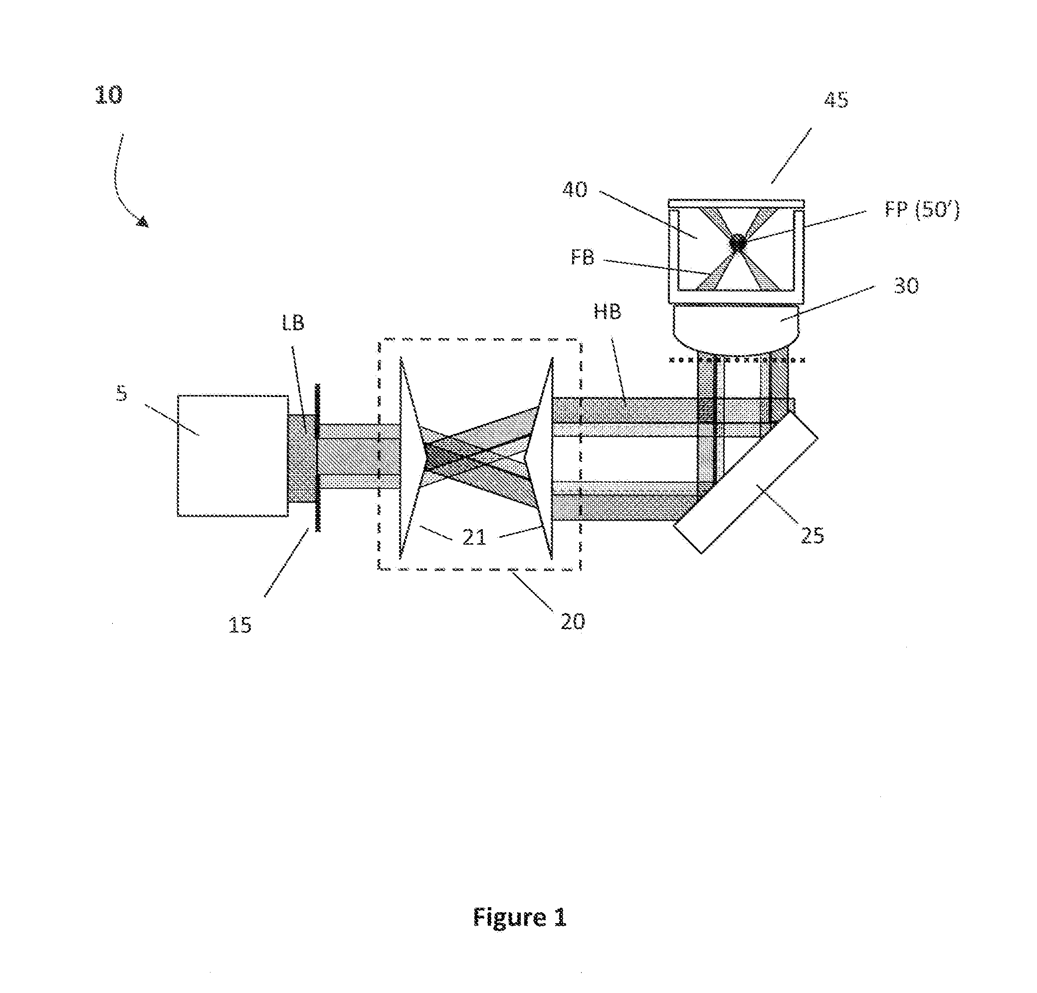
[0026]A novel optical trapping apparatus and methods for using the same are disclosed. This innovative optical trapping technique utilizes the radiative pressure of light to trap and hold transparent (non-absorbing) airborne particles while the photophoretic force is able to trap absorbing particles in the same optical geometry formed of a single shaped laser beam. The radiative pressure force results from the transport of momentum from photons to a particle. More particularly, radiative pressure forces are a combination of a gradient force and a scattering force. If a particle is near the focus of a laser beam, the gradient force will pull the particle back toward the high intensity region at the focus, providing the restoring force required to trap a particle. On the other hand, the scattering force, which results from the transfer of momentum from photons scattered off a particle, pushes the particle in the direction of light propagation and does not provide the required restorin...


PUM


Abstract

Embodiments of the present invention are directed to systems and methods for trapping and holding airborne particles. In the various embodiments, an optical trap is provided which uses a focused hollow-beam for trapping and holding both absorbing and non-absorbing airborne particles. The optical trap comprises: a trapping region where a particle can be present to be trapped; a light source for generating a coherent beam of light; optics for forming a hollow beam having a ring geometry from the coherent beam of light; and a focusing element for focusing the hollow beam to a point in the trapping region. In this arrangement, the particle is trapped at or near the focal point of the focused hollow beam.

Description

GOVERNMENT INTEREST[0001]The invention described herein may be manufactured, used and licensed by or for the U.S. Government without the payment of royalties thereon.[0002]Research underlying this invention was supported by the Defense Threat Reduction Agency (DTRA) under contract numbers HDTRA1310184 and HDTRA1514122, with U.S. Army Research Laboratory mission funds under Cooperative Agreement Number W911NF-12-2-0019.BACKGROUND OF THE INVENTION[0003]1. Field[0004]Embodiments of the present invention are generally directed to trapping and holding airborne particles, and more particularly, to optical traps which use a focused hollow-beam for trapping and holding both absorbing and non-absorbing airborne particles.[0005]2. Description of Related Art[0006]Airborne particles pose many problems. The ability to trap airborne particles for inspection and / or measurement is important for many applications. Conventional techniques to optically trap airborne particles use either radiative pres...

Claims


Application Information

Patent Timeline
IPC IPC(8): G21K1/00H05H3/04
CPCH05H3/04G21K1/006G01N2015/1493G01N2015/1497G01N15/1056G01N15/1434G01N15/1484G02B27/0018G02B21/32
Inventor PAN, YONGLEREDDING, BRANDON F.
Owner US SEC THE ARMY THE
Why Eureka
Try Eureka