Molded stator, molded electric motor, and air conditioner

Inactive Publication Date: 2016-09-08
MITSUBISHI ELECTRIC CORP
View PDF8 Cites 1 Cited by
  • Summary
  • Abstract
  • Description
  • Claims
  • Application Information

AI Technical Summary

Benefits of technology

[0012]With the molded stator of the present invention, because the molding pressure on a lead-out component during molding is increased, the lead-out component is pressed in a radial direction with a greater force so as to come into contact with the molding die so that the positioning in the radial direction can be made.

Problems solved by technology

However, with this type of configuration, ingress of fluid tends to occur through a gap or an interface between the outer frame of the molded electric motor and the wire lead-out component or through a gap or an interface between the wire lead-out component and the lead wire.
Therefore, heretofore, there has been a problem in that it is necessary to perform secondary processing such as the application of a sealing material or attachment of tape, which is measures of ensuring the molded electric motor, has waterproof properties.

Method used


Image

  • Molded stator, molded electric motor, and air conditioner
  • Molded stator, molded electric motor, and air conditioner
  • Molded stator, molded electric motor, and air conditioner

Examples


embodiment

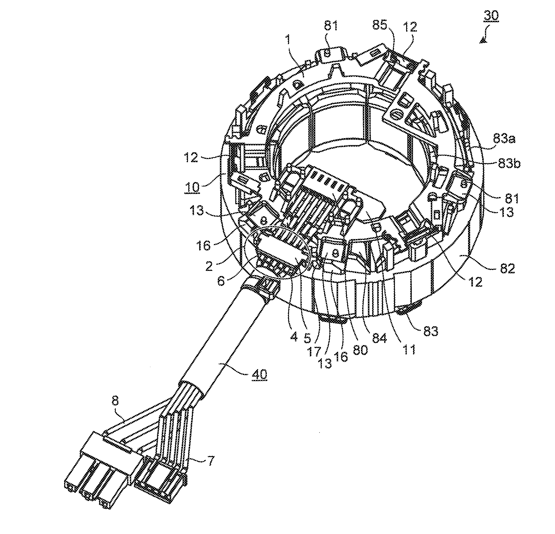
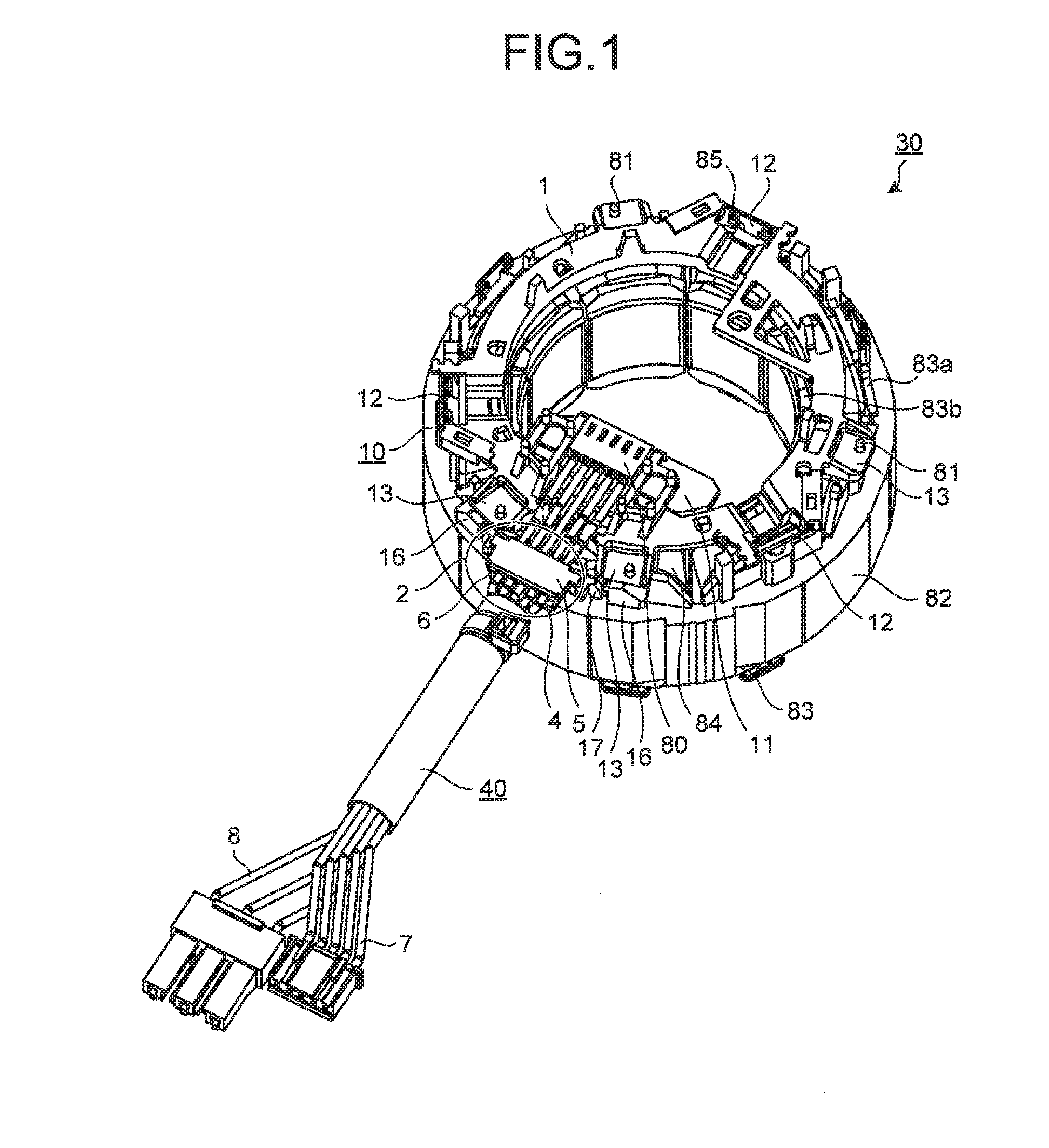
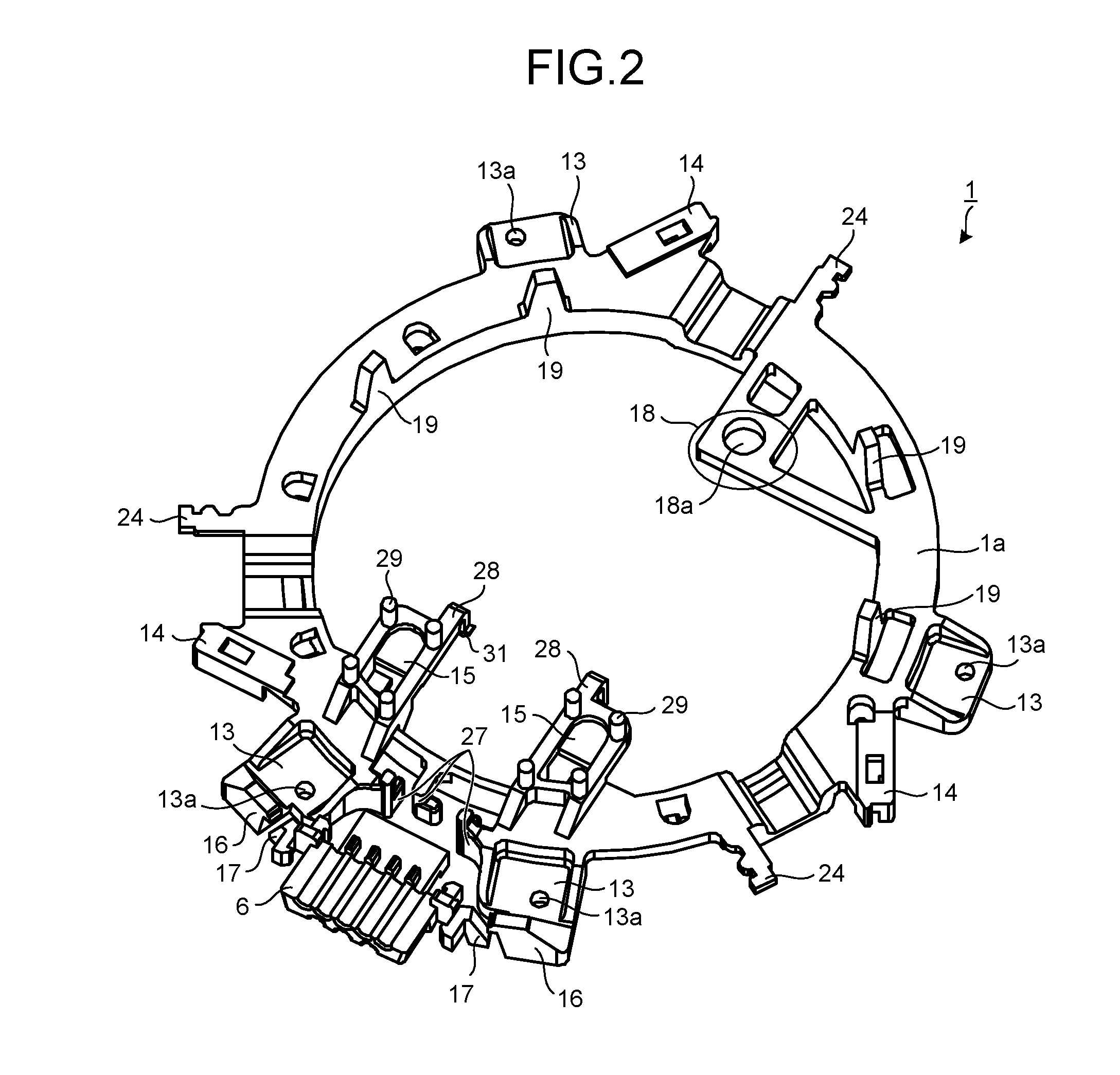
[0030]FIG. 1 is a perspective view of a stator assembly of an electric motor according to an embodiment of the present invention as viewed from a substrate side. FIG. 2 is a perspective view of a lead-wire wiring component illustrated in FIG. 1. FIG. 3 is a perspective view of the lead-wire wiring component illustrated in FIG. 2 as viewed from a rear surface (an opposite surface). FIG. 4 is an enlarged view of a lead-wire terminal holding unit included in the lead-wire wiring component illustrated in FIG. 2. FIG. 5 is an enlarged view of a lead-out component included in the lead-wire wiring component illustrated in FIG. 2 and the periphery of the lead-out component. FIG. 6 is an enlarged view of a substrate holding unit included in the lead-wire wiring component illustrated in FIG. 2 and the periphery of the substrate holding unit. FIG. 7 is an enlarged view of the substrate holding unit and the periphery thereof as viewed from a direction different from that of FIG. 6. FIG. 8 is a ...


PUM


Abstract

The present invention is a molded stator including a stator and a substrate. The molded stator includes: a donut-shaped lead-wire wiring component that wires power-supply lead wires to a winding wire of the stator and that wires sensor lead wires to the position detection circuit; a lead-out component that leads out the power-supply lead wires and the sensor lead wires to outside of the molded stator; a power-supply lead-wire holding component that holds the power-supply lead wires; and a sensor-lead-wire holding component that holds the sensor lead wires. The lead-out component is connected to a latching part that latches the sensor-lead-wire holding component and includes projections as plane parts that are substantially perpendicular to a radial direction of the stator on the radially outer side.

Description

FIELD[0001]The present invention relates to a molded stator, a molded electric motor, and an air conditioner.BACKGROUND[0002]It is conventional to install a molded electric motor as a fan motor in the indoor-device or the outdoor-device of an air conditioner. In a molded electric motor, a stator is molded from mold resin to form an outer frame thereof, and a rotor is placed movably on an inner periphery side of the outer frame. In the molded electric motor, a wire lead-out component for drawing a lead wire from the stator or a wiring substrate to the outside is provided. The wire lead-out component is integrally molded with the stator and wiring components from mold resin.[0003]However, with this type of configuration, ingress of fluid tends to occur through a gap or an interface between the outer frame of the molded electric motor and the wire lead-out component or through a gap or an interface between the wire lead-out component and the lead wire. Therefore, heretofore, there has ...

Claims


Application Information

Patent Timeline
Patent Type & Authority Applications(United States)
IPC IPC(8): H02K5/22F25D17/06H02K15/08H02K15/02H02K5/02H02K11/21
CPCH02K5/225H02K5/02F25D17/06H02K15/08H02K15/02H02K11/21H02K29/08H02K3/522
Inventor URABE, YUTOASO, HIROKISAKANOBE, KAZUNORIYAMAMOTO, MINEOISHII, HIROYUKIOYA, JUNICHIRO
Owner MITSUBISHI ELECTRIC CORP
Why Eureka
Try Eureka