A high-altitude bare cable insulation installation device

A cable insulation and cable technology, which is applied in the direction of overhead line/cable equipment, insulation/armored cable repair equipment, etc., can solve problems such as hidden dangers, cable safety, and difficult manual operation, so as to achieve high installation efficiency and stable power transmission , the effect of easy operation

Inactive Publication Date: 2020-09-01
WUHAN UNIV OF SCI & TECH
View PDF7 Cites 0 Cited by
  • Summary
  • Abstract
  • Description
  • Claims
  • Application Information

AI Technical Summary

Problems solved by technology

[0002] In the process of power transmission, the exposed high-voltage cables in the sky have potential safety hazards, which are easy to cause discharge and short circuit, so it is necessary to install an insulating layer on the high-voltage cables
Since the high-voltage cables are erected on the transmission tower, manual operation is extremely difficult and the risk factor is high

Method used


Image

  • A high-altitude bare cable insulation installation device
  • A high-altitude bare cable insulation installation device
  • A high-altitude bare cable insulation installation device

Examples


Embodiment 1

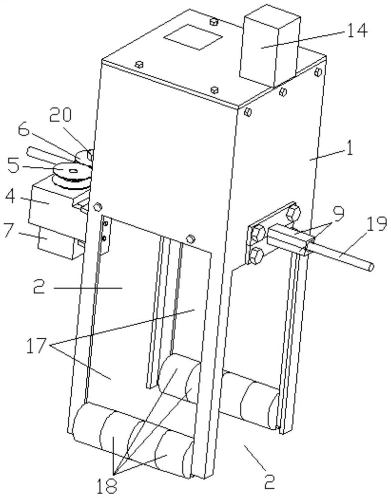
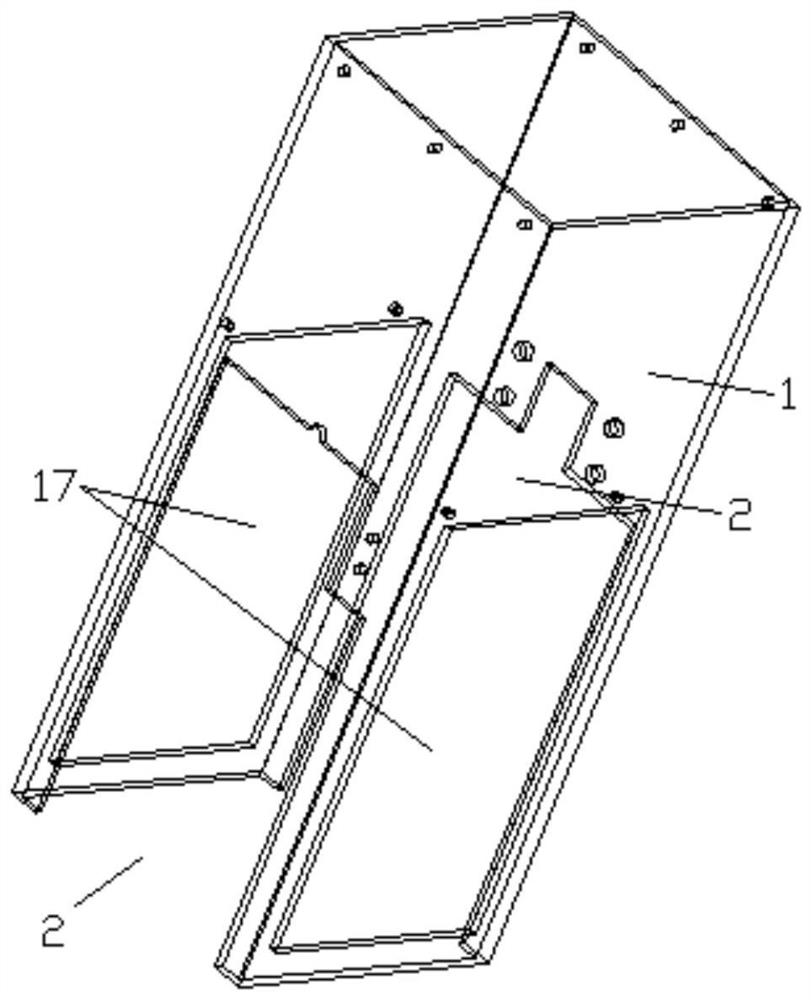
[0041] On the basis of the above structure, in this embodiment, openings 17 are provided on the opposite side walls of the box body 1. The openings 17 are in the shape of a "mouth", and each opening 17 is respectively provided with a plurality of counterweights. Block 18, each counterweight 18 is provided with a bayonet socket, directly counterweight 18 is stuck on the bottom of opening two 17 by bayonet. The weights of the parts of the box body 1 positioned at both sides of the cable 19 are adjusted by the counterweight 18 to make them equal, so as to ensure that the box body 1 is erected on the cable 19 stably and ensure the stability of the insulation layer installation.

[0042] It should be noted that the number of counterweights 18 at the two openings 17 may be inconsistent, and the weight of each counterweight 18 may also be inconsistent, as long as the box body 1 is erected on the cable 19 stably.

Embodiment 2

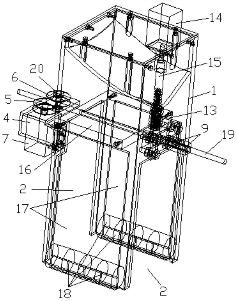
[0044] On the basis of Embodiment 1, in this embodiment, a support positioning plate 16 is installed horizontally and fixedly in the box body 1, and the support positioning plate 16 is integrally formed with the box body 1, or is detachably connected with the box body 1 by bolts. When the box body 1 and the edge of the supporting positioning plate 16 are respectively provided with screw holes that cooperate with the bolts; The locating groove 21 that cooperates with the cable 19 is provided with, and the stability of the box body 1 sliding on the cable 19 is increased by supporting the locating plate 16 and the locating groove 21, so as to ensure the quality of the insulating layer installation.

[0045] It should be noted that the positioning groove 21 can be arranged on the lower surface of the supporting positioning plate 16, or can be arranged on the upper surface of the supporting positioning plate 16. When the positioning groove 21 is arranged on the upper surface of the ...

Embodiment 3

[0048] On the basis of Embodiment 2, in this embodiment, the traveling mechanism includes a mounting plate 4, a driving wheel 5, a driven wheel 6 and a driving member, and the mounting plate 4 is detachably mounted on the corresponding opening 12, and the mounting plate 4 is installed The specific method is as follows: the position on the side of the opening 2 on the box body 1 is vertically fixed with a U-shaped fixing block by bolts, and the bottom of the U-shaped fixing block and the box body 1 are respectively provided with screw holes that cooperate with the bolts; A pair of screw holes are oppositely arranged on both sides of the U-shaped fixed block, and the mounting plate 4 is L-shaped. One end of the mounting plate 4 is provided with a through hole cooperating with the above-mentioned screw holes, and the positioning bolts 8 pass through one of the screw holes successively. hole and another screw hole to connect the mounting plate 4 and the U-shaped fixed block togethe...


PUM


Abstract

The invention relates to a high-altitude bare cable insulating layer adding device, and the device comprises a box body, a walking mechanism, hot melting mechanisms and a forming mechanism. The box body is hollow, and the bottom is open; first openings communicated with the bottom of the box body are formed in the two opposite side walls of the box body respectively, and cavities, located above the first openings, in the box body are divided into storage hoppers used for storing insulating particles through partition plates; feeding ports and discharging ports are formed in the tops and the bottoms of the storage hoppers respectively. The hot melting mechanisms is fixedly arranged in the storage hopper and is used for hot melting of the insulating particles; the walking mechanism is fixedly mounted at one of the first openings and is used for driving the box body to slide along the cable; and the forming mechanism is fixedly arranged at the other first opening, is positioned below thehot melting mechanism, is communicated with the discharge ports through a blanking channel, and is used for adding the hot-melted insulating particles on the cable. The beneficial effects of the invention are that the device can walk on a high-altitude exposed high-voltage cable, enables the insulating layer to be disposed on the high-voltage cable, is simple in operation, is high in installationefficiency, and is safe and reliable.

Description

technical field [0001] The invention relates to the technical field of cable processing equipment, in particular to a high-altitude exposed cable insulation layer installation device. Background technique [0002] In the process of power transmission, the exposed high-voltage cables in the sky have potential safety hazards, which are likely to cause discharge and short circuit. Therefore, it is necessary to install an insulating layer on the high-voltage cables. Since the high-voltage cables are erected on the transmission tower, manual operation is extremely difficult and the risk factor is high. Contents of the invention [0003] The technical problem to be solved by the present invention is to provide a high-altitude exposed cable insulation layer installation device, which can walk on the high-altitude exposed high-voltage cable and install the insulation layer on the high-voltage cable. The operation is simple, the installation efficiency is high, and it is safe. rel...

Claims


Application Information

Patent Timeline
Patent Type & Authority Patents(China)
IPC IPC(8): H02G1/02H02G1/16
CPCH02G1/02H02G1/16
Inventor 陈亚琦时朵刘昌明王佳松赵熙桐朱吉顺刘启浪
Owner WUHAN UNIV OF SCI & TECH
Why Eureka
Try Eureka