Method of forming a component from a green part

a technology of green parts and components, which is applied in the direction of turbines, machines/engines, stators, etc., can solve the problems of undesirable and/or impractical use of powder injection molding to manufacture components such as green parts, and relatively difficult molds

Inactive Publication Date: 2016-09-15
PRATT & WHITNEY CANADA CORP
View PDF7 Cites 4 Cited by
  • Summary
  • Abstract
  • Description
  • Claims
  • Application Information

AI Technical Summary

Benefits of technology

[0004]In one aspect, there is provided a method of forming a component from a part in a green state, the method comprising: selecting at least one first portion of the part to undergo a different local volume reduction from at least one second portion of the part to obtain the component; providing the part in the green state including: the at least one first portion having a first volume of powder material VP1 and a first volume of binder VB1, the at least one first portion having a first solid loading defined as VP1 / (VP1+VB1), and the at least one second portion having a second volume of powder material at least one second portion VP2 and a second volume of binder VB2, the at least one second portion having a second solid loading defined as VP2 / (VP2+VB2), the first and second solid loadings having different values from one another; and debinding and sintering the part to obtain the component, the different values of the first and second solid loadings producing the different local volume reduction in the at least one first portion with respect to the at least one second portion.

Problems solved by technology

Moreover, some gas turbine engine panel components, such as for example some combustor heat shield panels, may have features which are relatively hard to mold.
Accordingly, manufacturing these components using a molding process while being able to easily remove the component from the mold cavity may require the use of a mold with a complex configuration, which may render the use of a molding process such as powder injection molding to manufacture these components undesirable and / or impractical.

Method used


Image

  • Method of forming a component from a green part
  • Method of forming a component from a green part
  • Method of forming a component from a green part

Examples


Embodiment Construction

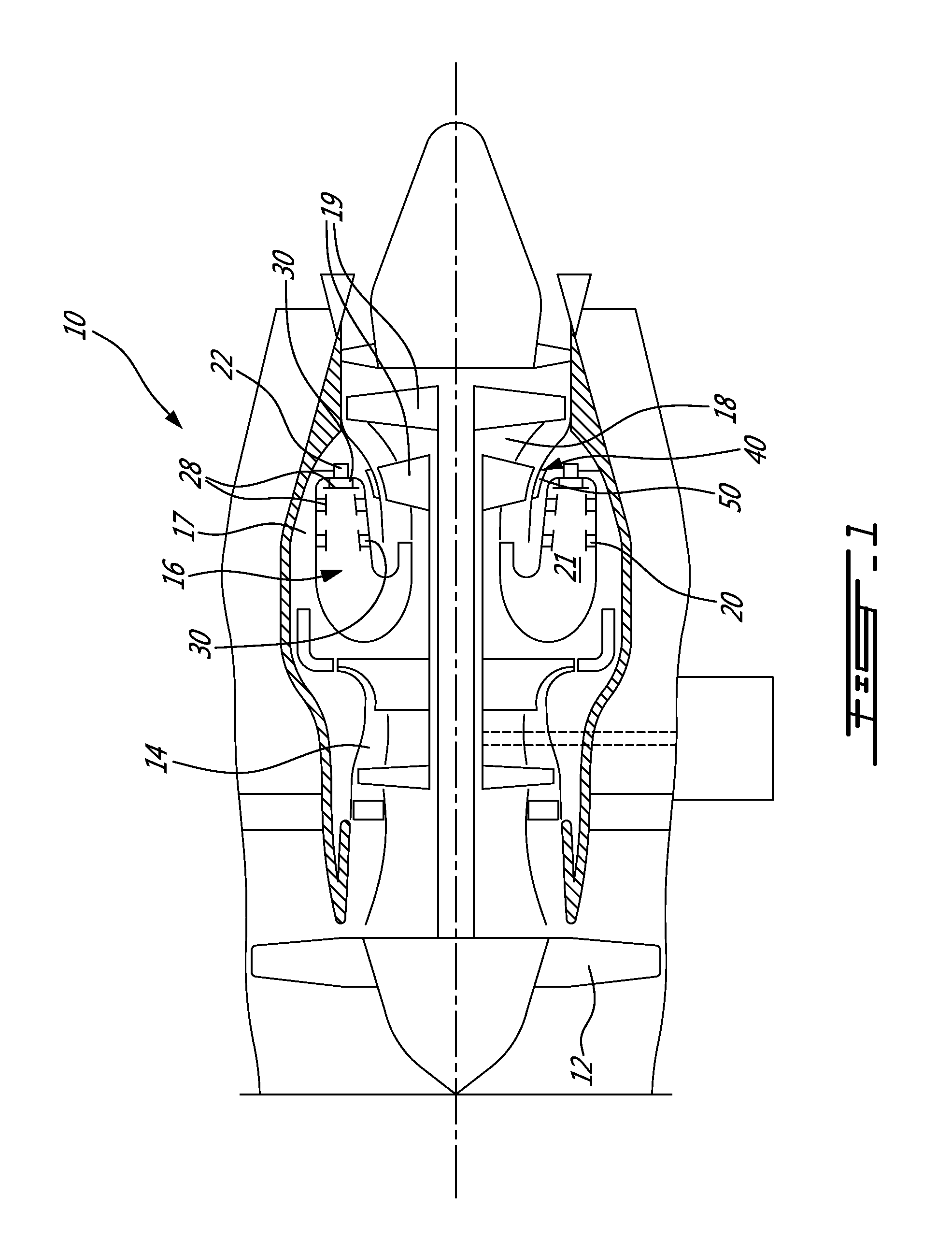
[0015]FIG. 1 illustrates a gas turbine engine 10 of a type preferably provided for use in subsonic flight, generally comprising in serial flow communication a fan 12 through which ambient air is propelled, a compressor section 14 for pressurizing the air, a combustor 16 in which the compressed air is mixed with fuel and ignited for generating an annular stream of hot combustion gases, and a turbine section 18 for extracting energy from the combustion gases.

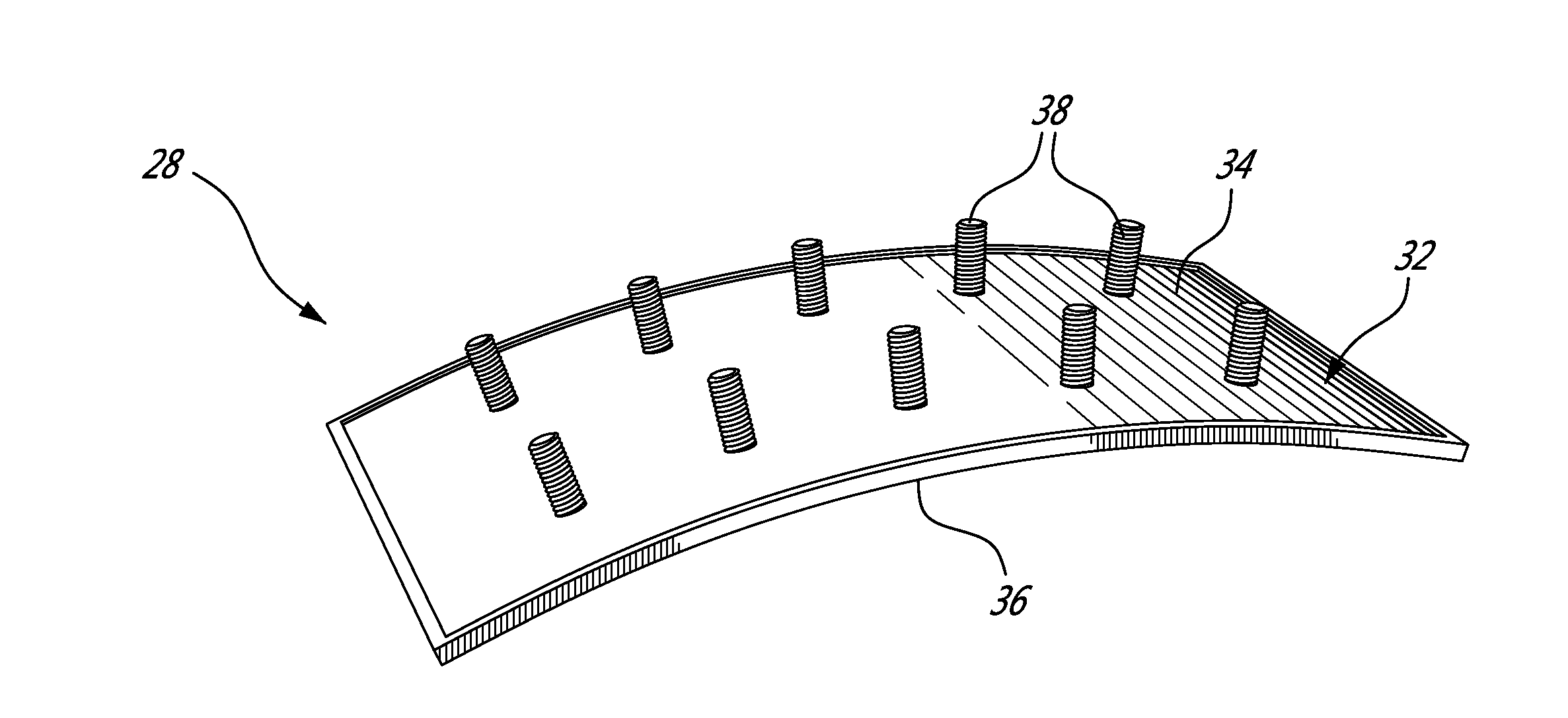
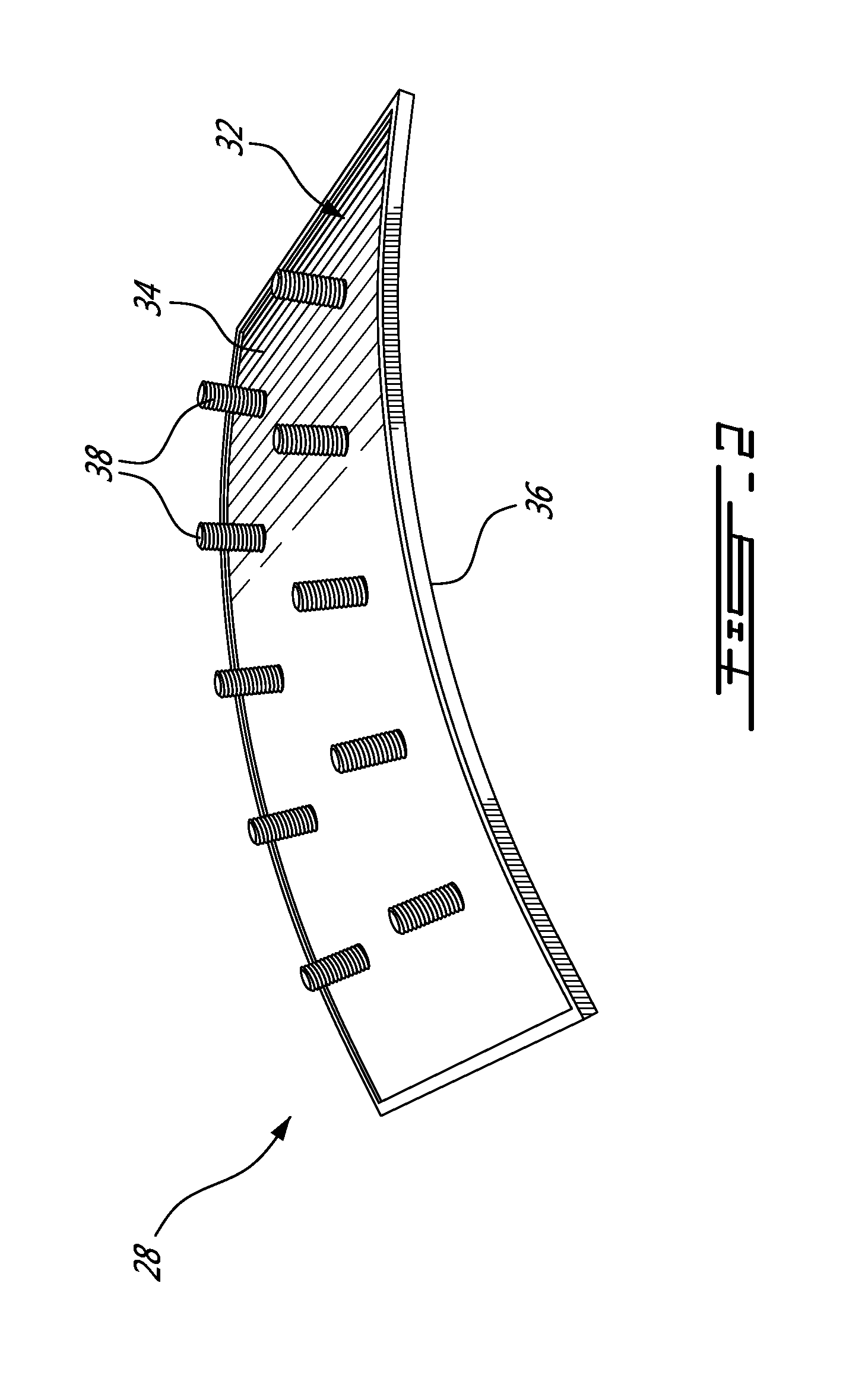
[0016]The combustor 16 is housed in a plenum 17 supplied with compressed air from compressor section 14. The combustor 16 typically comprises a combustor shell 20 defining a combustion chamber 21 and a plurality of fuel nozzles 22 for atomizing fuel, which are typically equally circumferentially distributed on the dome end panel of the combustor shell 20 in order to permit a substantially uniform temperature distribution in the combustion chamber 21 to be maintained. The combustor shell 20 is typically made out from sheet metal.

[0...


PUM

PropertyMeasurementUnit
temperatureaaaaaaaaaa
melting temperatureaaaaaaaaaa
volumeaaaaaaaaaa

Abstract

A method of forming a component from a part in the green state, including selecting at least one first portion of the part to undergo a different local volume reduction from at least one second portion to obtain the component. The green part is provided with the first portion(s) having a first solid loading and the second portion(s) having a second solid loading different from the first solid loading, then debound and sintered to obtain the component. The different first and second solid loadings produce the different local volume reduction in the first portion(s). The first portion(s) can be selected by determining a resulting final shape obtained from debinding and sintering a green part having a uniform first volumetric proportion of binder, and selecting the first portion(s) requiring a different local deformation than that producing the resulting final shape to obtain a desired final shape.

Description

TECHNICAL FIELD[0001]The application relates generally to the manufacturing of components from green parts and, more particularly, to powder injection molding processes.BACKGROUND OF THE ART[0002]When manufacturing complex parts using powder injection molding, the volume reduction of the part occurring during sintering is often anisotropic, i.e. the deformations caused by the volume reduction are often more important in one direction when compared to the other. Accordingly, the shape of the part may change during sintering, which may prevent parts from being manufactured within tight dimensional tolerances.[0003]Moreover, some gas turbine engine panel components, such as for example some combustor heat shield panels, may have features which are relatively hard to mold. Such features may include, for example, a curved shape, angled retention elements and / or angled cooling holes. Accordingly, manufacturing these components using a molding process while being able to easily remove the ...

Claims


Application Information

Patent Timeline
Patent Type & Authority Applications(United States)
IPC IPC(8): B22F3/22B22F7/02B22F5/00B22F3/105
CPCB22F7/02B22F3/105B22F3/225B22F5/009B22F3/02B22F3/1021B22F7/06B22F2003/023B22F2999/00F01D9/04F01D25/246F05D2230/22Y02T50/60Y02P10/25B22F2207/01
Inventor SCALZO, ORLANDOCAMPOMANES, MARCPOITRAS, GUILLAUME
Owner PRATT & WHITNEY CANADA CORP
Why Eureka
Try Eureka