Method for Charging an Intermediate Circuit Capacitor

a technology of intermediate circuit capacitor and capacitor, which is applied in the direction of dynamo-electric converter control, propulsion by batteries/cells, transportation and packaging, etc., can solve the problems of large potential risk for maintenance personnel, high cost, and large weight of said components

Active Publication Date: 2014-02-13
ROBERT BOSCH GMBH +1
View PDF5 Cites 7 Cited by
  • Summary
  • Abstract
  • Description
  • Claims
  • Application Information

AI Technical Summary

Benefits of technology

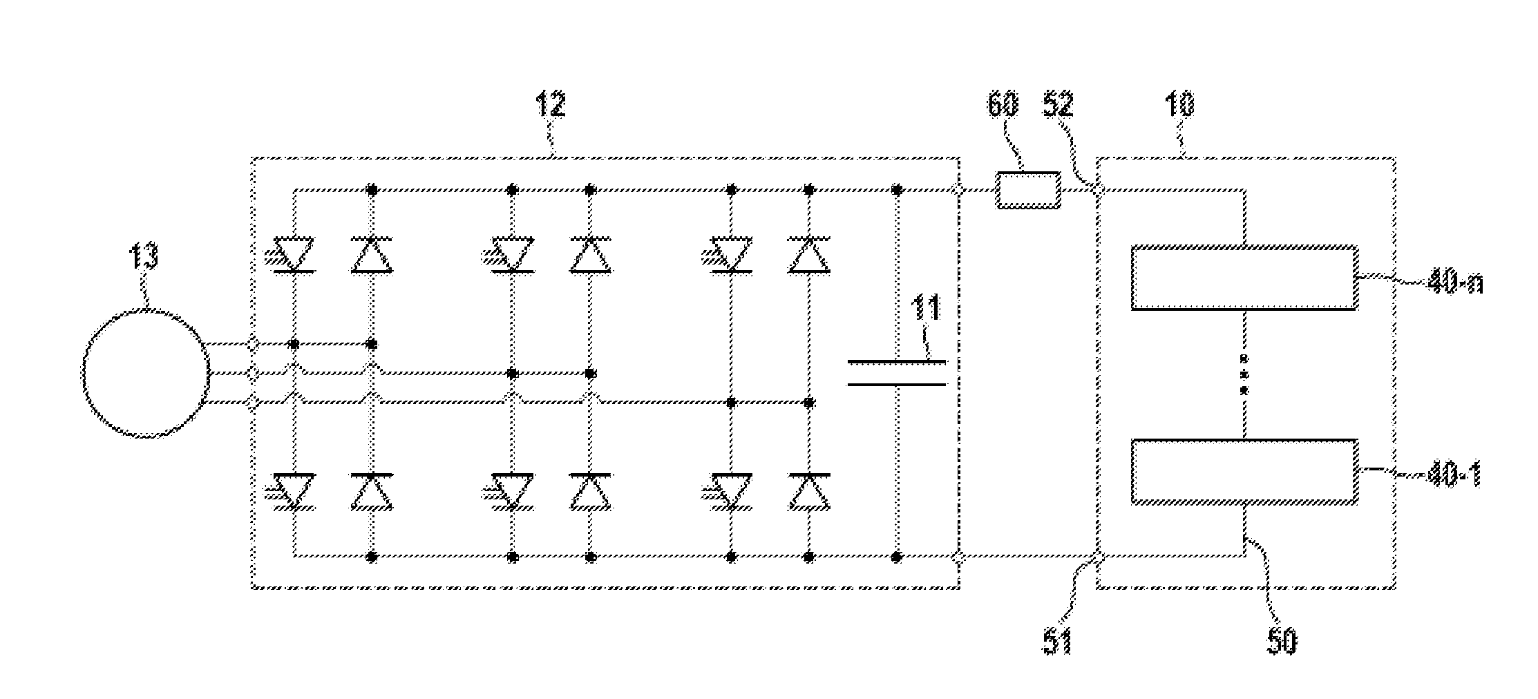
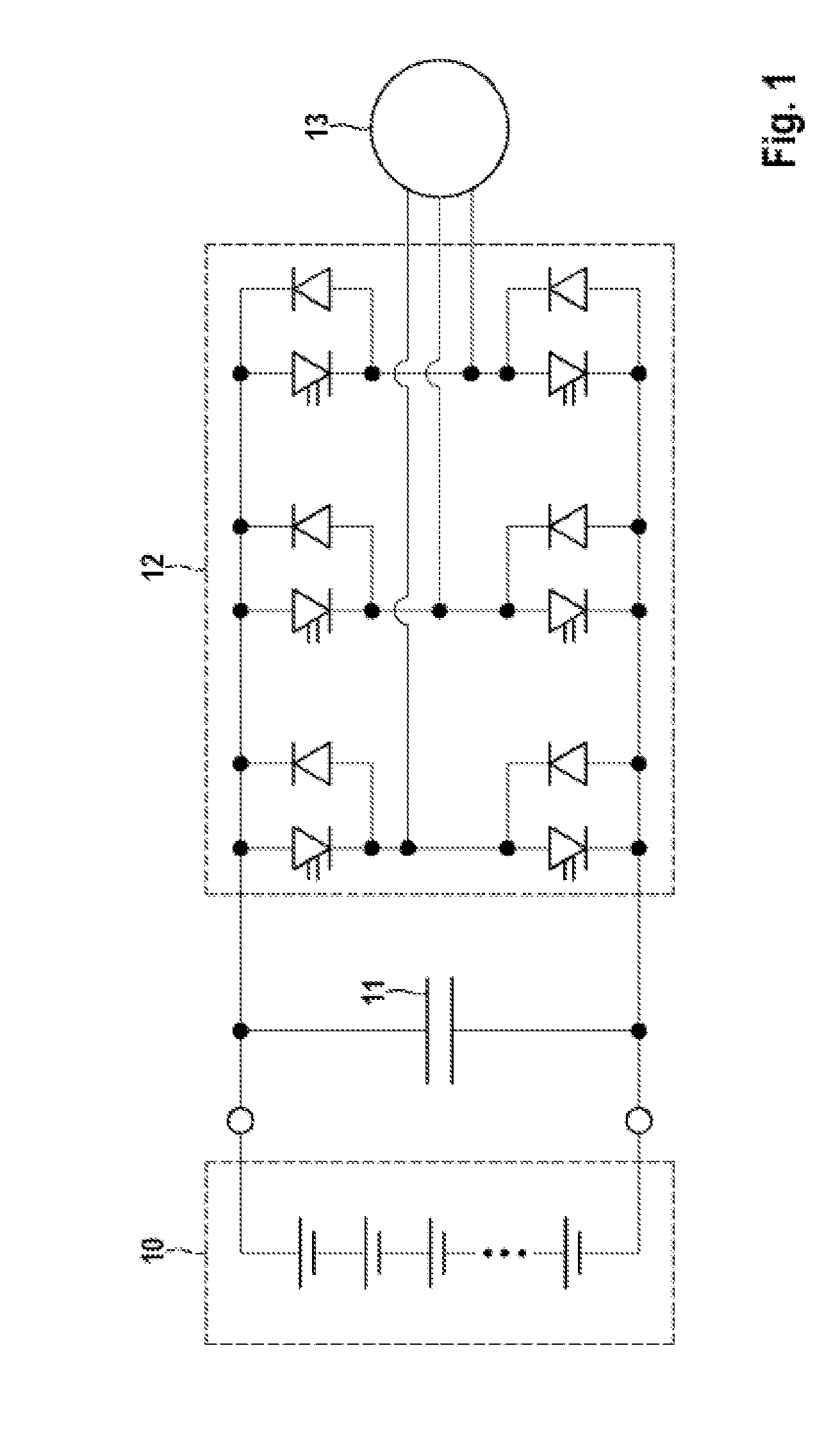
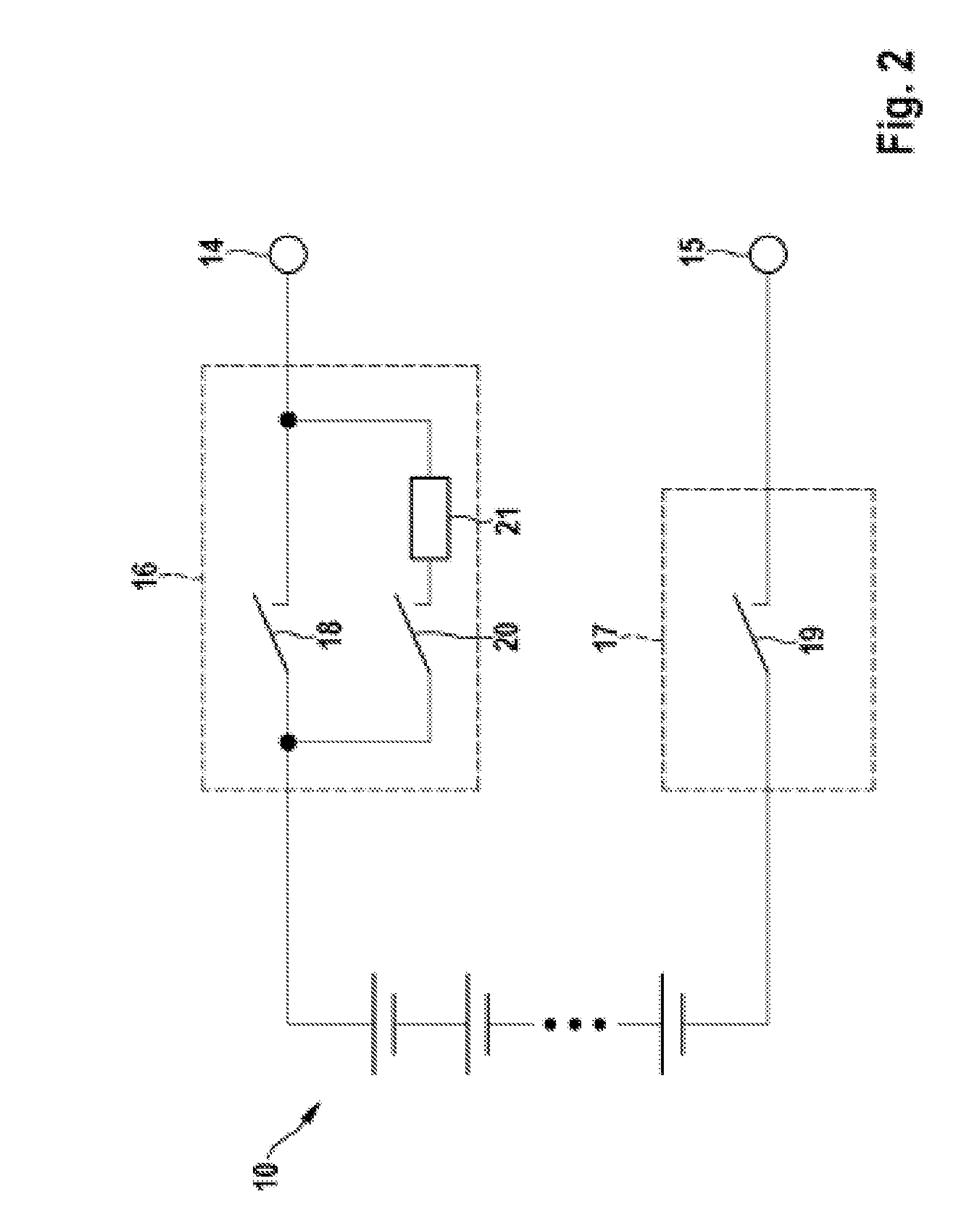
[0007]According to the invention, a method for charging an intermediate circuit capacitor in an electric drive unit with an electric motor is provided. The intermediate circuit capacitor is charged by an intermediate circuit current, which is provided by a battery, whose output voltage can be adjusted to one of a plurality of voltage values. The available voltage values may also be temporally averaged voltage values which are generated by the use of known modulation methods, for example pulse width modulation. The method is characterized by the fact that, first, a setpoint value of the intermediate circuit current is fixed and an actual value for the intermediate circuit current is determined. Then, the actual value for the intermediate circuit current is compared with the setpoint value for the intermediate circuit current. On the basis of this comparison, an optimum output voltage for the battery is determined, which output voltage is suitable for favorably influencing the development of the intermediate circuit current over time. This optimum output voltage of the battery is finally adjusted. The provided method has the advantage that it manages without any charging switches and charging resistor, which are expensive, large and heavy.

Problems solved by technology

However, it is problematic that compensation currents between the battery cells connected in parallel may arise owing to cell capacitances and voltages which are not exactly identical.
Owing to the high DC voltage of the series-connected battery cells, there is otherwise a considerable potential risk for maintenance personnel or the like.
Said components are not only expensive but are also large and heavy, which is particularly disruptive for the use in mobile applications such as electric motor vehicles.

Method used


Image

  • Method for Charging an Intermediate Circuit Capacitor
  • Method for Charging an Intermediate Circuit Capacitor
  • Method for Charging an Intermediate Circuit Capacitor

Examples


first embodiment

[0028]FIG. 4 shows the coupling unit 30, which has an inverter 34 which can in principle only connect one of the two inputs 31, 32 to the output 33, while the respective other input 31, 32 is decoupled from the output 33. The inverter34 can have a particularly simple realization as an electromechanical switch.

second embodiment

[0029]FIG. 5 shows the coupling unit 30, in which a first and a second switch 35 and 36 are provided. Each of the switches is connected between one of the inputs 31 and 32 and the output 33. In contrast to the embodiment shown in FIG. 4, this embodiment has the advantage that both inputs 31, 32 can also be decoupled from the output 33, with the result that the output 33 will have a high resistance. In addition, the switches 35, 36 can be implemented simply as semiconductor switches such as metal-oxide semiconductor field-effect transistors (MOSFETs) or insulated gate bipolar transistors (IGBTs), for example. Semiconductor switches have the advantage of a favorable price and a high switching speed, with the result that the coupling unit 30 can respond to a control signal or a change in the control signal within a short period of time and high switchover rates can be achieved.

[0030]FIG. 6 shows the second embodiment of the coupling unit in a simple semiconductor circuit, in which each...


PUM


Abstract

The disclosure relates to a method for charging an intermediate circuit capacitor in an electric drive unit comprising an electric motor. The intermediate circuit capacitor is charged by an intermediate circuit current that is supplied by a battery. The output voltage of the battery is settable to one or more voltage values. A target value of the intermediate circuit current is determined, and an actual value of the intermediate circuit current is ascertained. The actual value of the intermediate circuit current is then compared with the target value of the intermediate circuit current. An optimal output voltage of the battery is determined on the basis of the comparison of the actual value of the intermediate circuit current with the target value of the intermediate circuit current. Then, the optimal output voltage of the battery is set.

Description

[0001]The present invention relates to a method for charging an intermediate circuit capacitor in an electric drive unit with an electric motor and a control device for implementing the method according to the invention.PRIOR ART [0002]It would appear that in the future battery systems will be used increasingly both in stationary applications and in vehicles such as hybrid and electric vehicles. In order to be able to meet requirements set for a respective application in respect of voltage and available power, a high number of battery cells are connected in series. Since the current provided by such a battery needs to flow through all of the battery cells and a battery cell can only conduct a limited current, additional battery cells are often connected in parallel in order to increase the maximum current. This can be provided either by providing a plurality of cell coils within a battery cell housing or by external interconnection of battery cells. However, it is problematic that c...

Claims


Application Information

Patent Timeline
Patent Type & Authority Applications(United States)
IPC IPC(8): H02J7/00
CPCH02J7/0065H02J7/0013H02J7/345B60L50/51Y02T10/70Y02T10/72H02J2207/20
Inventor SCHMIDT, RALPHBUTZMANN, STEFANFINK, HOGER
Owner ROBERT BOSCH GMBH
Why Eureka
Try Eureka