Method for grasping texture-less metal parts based on bold image matching

a metal part and bold image technology, applied in the field of computer vision and industrial automation, can solve the problems of low matching accuracy, high complicity, and methods not suitable for texture-less metal parts

Active Publication Date: 2021-09-02
ZHEJIANG UNIV
View PDF0 Cites 0 Cited by
  • Summary
  • Abstract
  • Description
  • Claims
  • Application Information

AI Technical Summary

Benefits of technology

[0006]To overcome the defects of the aforesaid matching methods, the present invention provides a method for grasping texture-less metal parts based on BOLD image matching. The present invention puts forward a novel line segment direction definition method and improves the calculation method of distance functions for matching, thus being suitable for more general conditions and satisfying actual application requirements.

Problems solved by technology

However, this method is not suitable for texture-less metal parts the valid feature points of which cannot be extracted.
However, all these methods calculate the contours as a whole and may be influenced by external factors; the calculation complicity is high, the matching accuracy is low, and the final success rate of grasping is affected.
However, due to the BOLD's requirement for a description of line segments in the gradient direction, the BOLDs cannot be accurately matched in case of a change to the image contrast, thus resulting in a grasping failure.

Method used


Image

  • Method for grasping texture-less metal parts based on bold image matching
  • Method for grasping texture-less metal parts based on bold image matching
  • Method for grasping texture-less metal parts based on bold image matching

Examples


Embodiment Construction

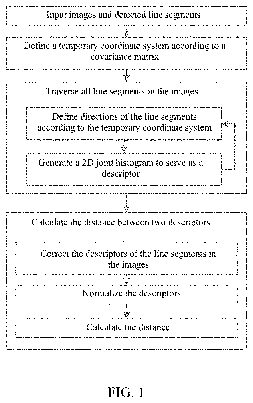
[0045]The present invention will be further explained below in conjunction with the accompanying drawings and embodiments. The flow diagram of the present invention is illustrated by FIG. 1.

[0046]A specific embodiment and an implementation process thereof of the present invention are as follows:

[0047]This embodiment is implemented with a U-shaped bolt as a texture-less metal part.

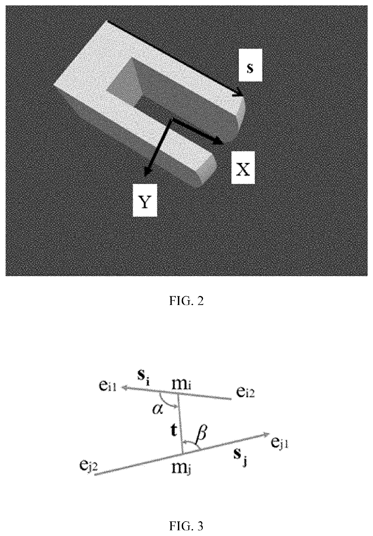
[0048]Step 1: a real texture-less metal part placed in a real environment is photographed by a real physical camera to obtain a real image; a texture-less metal part CAD model imported in a computer virtual scene is photographed by a virtual camera to obtain CAD template images; a foreground part of the input real image and the input CAD template images is extracted through a grabcut algorithm, a covariance matrix of the foreground part is calculated, and the direction of a temporary coordinate system is established.

[0049]The real image and the CAD template images are specifically processed as follows: a co...


PUM


Abstract

A method for grasping texture-less metal parts based on BOLD image matching comprises: obtaining a real image and CAD template images by photographing, extracting a foreground part of the input part image, calculating a covariance matrix of a foreground image, establishing the direction of a temporary coordinate system, and setting directions of line segments to point to a first or second quadrant of the temporary coordinate system; constructing a descriptor of each line segment according to an angle relation between the line segment and k nearest line segments, and matching the descriptors of different line segments in the real image and the CAD template images to obtain line segment pairs; and recognizing a processed pose through a PNL algorithm to obtain a pose of a real texture-less metal part, and then inputting the pose of the real texture-less metal part to a mechanical arm to grasp the part. The present invention can correctly match line segments, obtain an accurate pose of the part by calculation, successfully grasp the part, and satisfy actual application requirements.

Description

BACKGROUND OF THE INVENTION1. Technical Field[0001]The present invention relates to the technical field of computer vision and industrial automation, in particular to a method for grasping texture-less metal parts based on contrast-invariant bunch of lines descriptor image matching.2. Description of Related Art[0002]Grasping of texture-less metal parts has always been an important research interest in the field of computer vision and industrial automation, and is required in many application scenarios such as part recognition.[0003]The most common method for grasping textured objects is to extract and then match feature points (such as SIFT (scale-invariant feature transform) or SURF (speeded up robust features)) in templates and real images, and is high in efficiency and accurate. However, this method is not suitable for texture-less metal parts the valid feature points of which cannot be extracted.[0004]Most existing matching-based texture-less part grasping method are typically i...

Claims


Application Information

Patent Timeline
Patent Type & Authority Applications(United States)
IPC IPC(8): G06K9/62G06K9/00B25J15/00G06V10/422G06V10/44G06V10/50
CPCG06K9/6201B25J15/0033G06K9/00536G06V10/422G06V10/50G06V10/44G06V2201/06G05B2219/40564G06F18/22G06F2218/12
Inventor HE, ZAIXINGZHAO, XINYUEJIANG, ZHIWEI
Owner ZHEJIANG UNIV
Why Eureka
Try Eureka