
Boring machine

Inactive Publication Date: 2016-09-15
CHIEN JU CHUAN
View PDF0 Cites 2 Cited by
  • Summary
  • Abstract
  • Description
  • Claims
  • Application Information

AI Technical Summary

Benefits of technology

The present invention is about a boring machine that has a headstock unit with a power design that can shift gears to high, medium, or low. This allows the boring machine to be used for a wide range of machining tasks. The machine includes a table, a headstock unit, a drive unit, a seat, and a power unit. The seat combines the headstock unit and the drive unit, which drives the headstock unit along a linear axis. The power unit powers the headstock unit to rotate at different speeds to meet different machine processing needs. This design allows the boring machine to be more versatile and efficient in machining tasks.

Problems solved by technology

However, in an actual operation, this kind of processing machine does not perform the processing in a single mode on a single product; therefore, the processing tool should be replaced depending upon the object of processing and the processing procedure.
Accordingly, the operation mode of machining shaft in single speed is unable to comply with the actual need of operation.

Method used


Image

  • Boring machine
  • Boring machine
  • Boring machine

Examples


Embodiment Construction

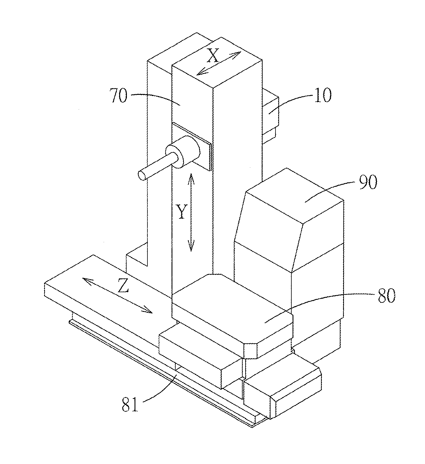
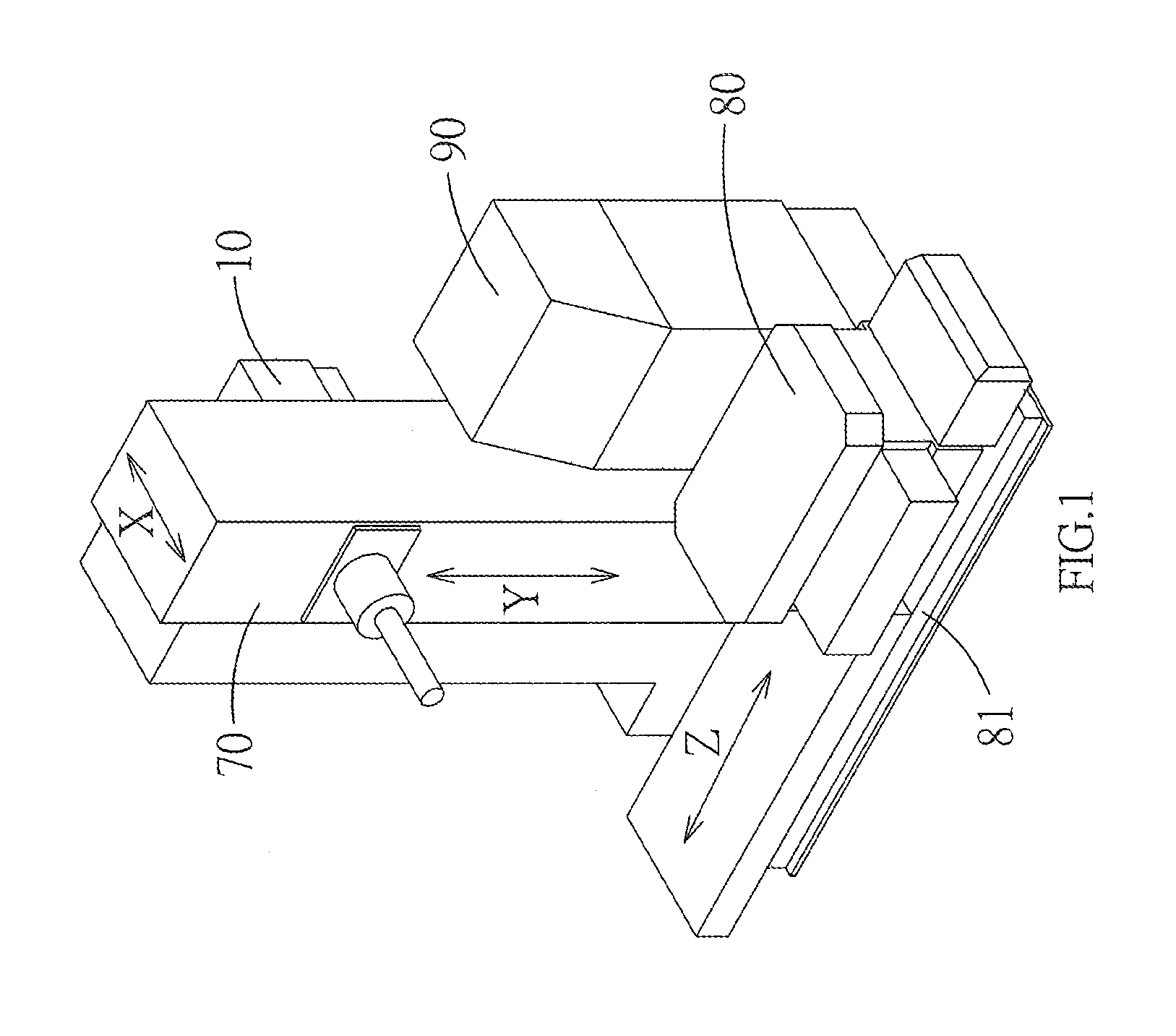
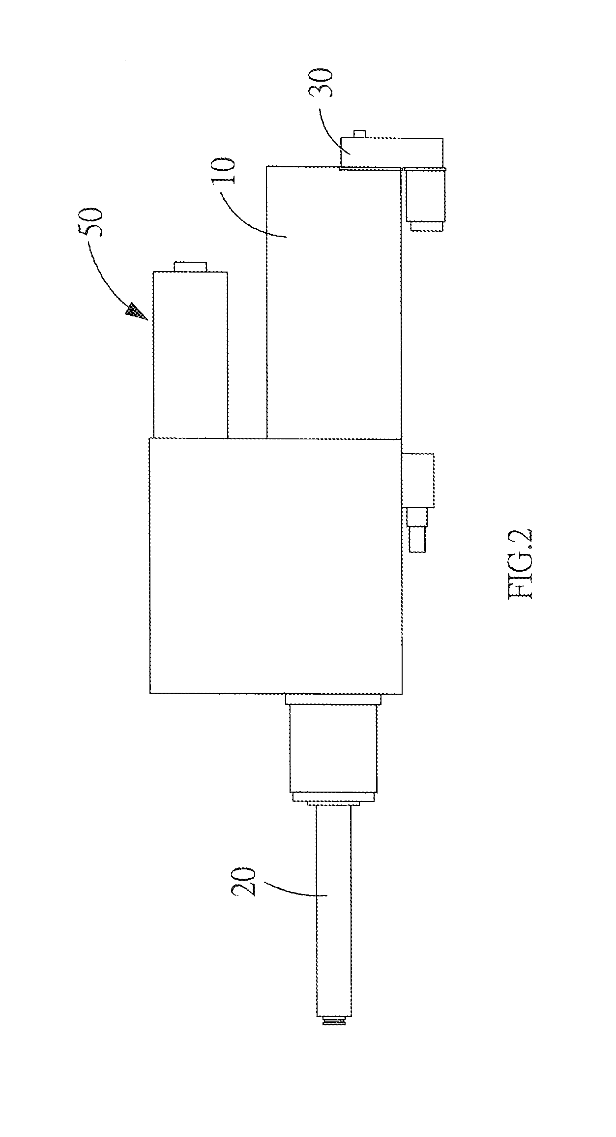
[0017]FIG. 1, FIG. 2, and FIG. 3 show a three-dimensional structural view of the boring machine, and a first schematic view and a second schematic view of the boring machine, according to the present invention. As shown in the drawings, the boring machine includes primarily a table 10, a headstock unit 20 installed on the table 10, a drive unit 30, a seat 40 and a power unit 50.

[0018]The headstock unit 20 is installed in the table 10 and is sheathed with at least a gnawing tooth member 21; a link rod 22 is sheathed inside the headstock unit 20 and a front end of the link rod 22 is provided with a blade barrel clip 23 which provides for clipping a blade (not shown in the drawings).

[0019]The drive unit 30 drives the headstock unit 20 to displace linearly along a first axis X, so that a processing blade can be fed in or discharged out of an end of the blade barrel clip 23 that clips the processing blade. The drive unit 30 is provided with a first power part 31 and a lead screw 32. The ...


PUM

PropertyMeasurementUnit
Speedaaaaaaaaaa

Abstract

The present invention discloses a boring machine which includes a table, a headstock unit which is installed on the table, a drive unit which drives the headstock unit to displace linearly along a first axis, a seat and a power unit. The seat provides for combining the headstock unit with the drive unit. The drive unit drives the headstock unit to displace linearly along the first axis, the power unit drives the headstock unit to rotate, and the power unit changes rotational speed by using the gnawing relation among main gears and speed-change gears in different sizes, so that the headstock unit can shift to different speed to cope with all kinds of machine processing.

Description

BACKGROUND OF THE INVENTION[0001](a) Field of the Invention[0002]The present invention relates to a boring machine, and more particularly to a boring machine with a headstock unit having a power design of shifting speed to high, medium or low gear, such that the boring machine can be used broadly in general machining.[0003](b) Description of the Prior Art[0004]Machine equipment, especially a lathe, milling machine, boring machine, planing machine or grinding machine, has taken a leading role in all kinds of machine processing. Currently, a CNC (Computer Numerically Controlled) machine has shown up for the processing automation and the improvement of processing speed and precision. Among the abovementioned machine equipment, the milling machine is utilized to process planar parts and the boring machine is used primarily to perform precision machining for holes; the plane processing and the hole processing are often used in the machine processing.[0005]For the ordinary boring machine,...

Claims


Application Information

Patent Timeline
IPC IPC(8): B23B39/10B23B39/04
CPCB23B39/10B23B2260/07B23B39/04
Inventor TSENG, FENG -WEN
Owner CHIEN JU CHUAN
Learn More