System and method of generating a pattern used to process a surface of a fabric through laser irradiation, and fabric created thereby

a technology of laser irradiation and fabric, which is applied in the direction of dyeing process, pattern making, transportation and packaging, etc., can solve the problems of large amount of water used in stonewashing and enzyme processes, and the manufacturing cycle requires extensive time to create stonewashed looks,

Active Publication Date: 2016-09-15
REVOLAZE LLC
View PDF1 Cites 74 Cited by
  • Summary
  • Abstract
  • Description
  • Claims
  • Application Information

AI Technical Summary

Benefits of technology

[0015]Other aspects of the invention, including apparatus, devices, systems, fabrics, non-transitory computer/machine readable media processes, and th

Problems solved by technology

However, traditional stonewash and/or enzyme processes have numerous drawbacks.
For example, each manufacturing cycle requires extensive time to create the stonewashed look.
Further, a significant amount of water is used during the stonewash and enzyme processes.
In addition, the handling and disposal of the enzymes and wastewater can require substantial attention to comply with environmental regulations.
However, ring spun denim is more costly than standard denim fabric due to the higher fiber count and relative

Method used


Image

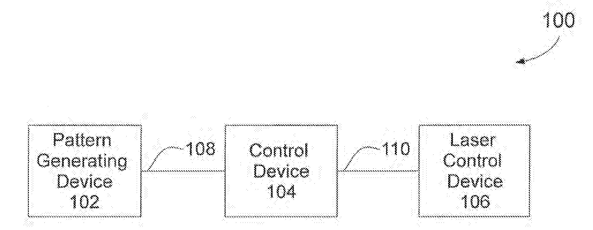
  • System and method of generating a pattern used to process a surface of a fabric through laser irradiation, and fabric created thereby
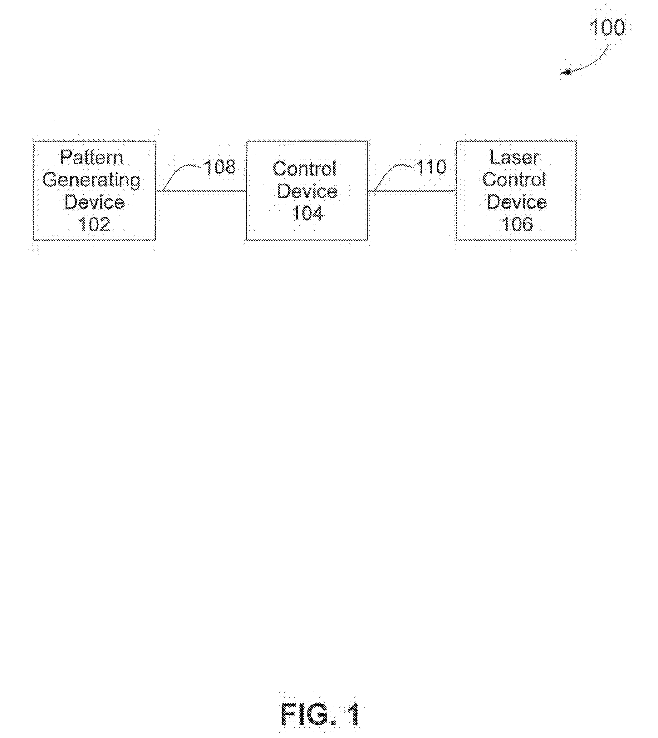
  • System and method of generating a pattern used to process a surface of a fabric through laser irradiation, and fabric created thereby
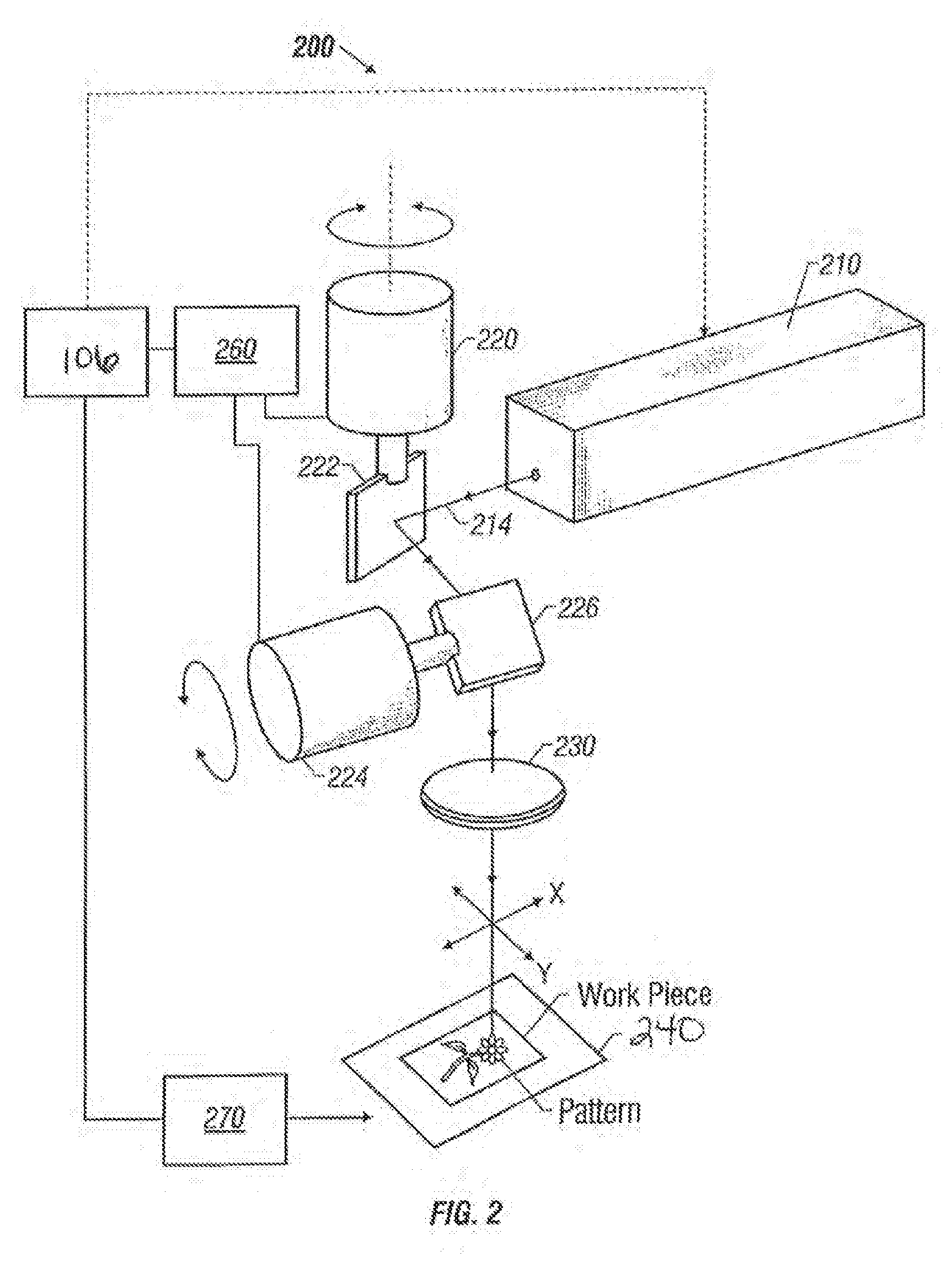
  • System and method of generating a pattern used to process a surface of a fabric through laser irradiation, and fabric created thereby

Examples


Embodiment Construction

[0044]Reference will now be made in detail to exemplary embodiments and methods of the invention as illustrated in the accompanying drawings, in which like reference characters designate like or corresponding parts throughout the drawings. It should be noted, however, that the invention in its broader aspects is not limited to the specific details, representative devices and methods, and illustrative examples shown and described in connection with the exemplary embodiments and methods.

[0045]This description of exemplary embodiments is intended to be read in connection with the accompanying drawings, which are to be considered part of the entire written description. In the description, relative terms such as “horizontal,”“vertical,”“up,”“down,”“upper,”“lower,”“right,”“left,”“top,” and “bottom” as well as derivatives thereof (e.g., “horizontally,”“downwardly,”“upwardly,” etc.) should be construed to refer to the orientation as then described or as shown in the drawing figure under dis...


PUM

PropertyMeasurementUnit
Lengthaaaaaaaaaa
Thicknessaaaaaaaaaa
Coloraaaaaaaaaa

Abstract

A method is provided of generating a pattern image used to form a pattern on a surface of a fabric using laser irradiation. A plurality of parameters associated with laser irradiation units are input into a user interface. The parameters include an area parameter, a laser irradiation unit density parameter, optionally a discontinuity parameter, and a dye removal parameter. A plurality of laser irradiation units arranged in a pattern area of a user interface based on computer processing of the inputted plurality of parameters is received for viewing at the user interface. The laser irradiation units collectively establish the pattern image for viewing by the user.

Description

CROSS-REFERENCE TO RELATED APPLICATION(S)[0001]This application is a continuation-in-part of U.S. application Ser. No. 14 / 491,597 filed on Sep. 19, 2014, which claims the benefit of priority of U.S. Provisional Application No. 61 / 879,844 filed Sep. 19, 2013 and U.S. Provisional Application No. 61 / 930,082 filed Jan. 22, 2014, the priorities of which are claimed herein.BACKGROUND OF THE INVENTION[0002]1. Field of the Invention[0003]The present invention generally relates to surface treatment of fabrics with one or more lasers and, more specifically, to a system and method for generating a pattern image used to process a surface of a fabric through laser irradiation (lasing), to the overall lasing process, and to the fabric resulting from such treatment having a pattern corresponding to the pattern image. In certain embodiments of the invention, processing of the fabric may be accomplished through the use of either multiple passes of a single laser or multiple lasers each lasing an ind...

Claims


Application Information

Patent Timeline
IPC IPC(8): B41M7/00
CPCB41M7/0009B41J2/455D06P5/13D06P5/15D06P5/2005D06Q1/02D06B11/0096D06C23/02Y10T428/2481
Inventor COSTIN, JR., DARRYL J.COLWELL, HEATH
Owner REVOLAZE LLC
Why Eureka
Try Eureka