This helps you quickly interpret patents by identifying the three key elements:
Problems solved by technology
Method used
Benefits of technology
Problems solved by technology
In this case, since the output of the Ar laser is not sufficient, an irradiation surface has a spot shape.
It is inferred that this is caused by a subtle shift of an optical system, a material of an optical member, a working error, dispersion of energy due to thermal conduction in a semiconductor film, and the like.
Method used
Image
Click on the blue label to locate the original text in one second.
Reading with bidirectional positioning of images and text.
Examples
embodiment 1
In fabricating steps of this embodiment, first, a method of fabricating films to be irradiated with a laser will be described. The films to be irradiated with the laser are three kinds of amorphous silicon films in the present specification. The present invention is effective for any film.
Any of the three kinds of amorphous silicon films are films formed by a plasma CVD method on a siliconoxide film with a thickness of 200 nm as an base film on a Corning 1737 glass substrate of 127 mm square as a substrate. The thickness of each of the amorphous silicon films is made 50 nm. This amorphous silicon film will be hereinafter referred to as a starting film.
(Fabricating procedure of film A)
The starting film is subjected to heat annealing at 450.degree. C. for one hour. This step is for reducing the hydrogen concentration in the amorphous silicon film. If the concentration of hydrogen in the film is excessively high, the film can not resist the laser energy, so that this step is required....
embodiment 2
In the case where the stripe pattern does not disappear well in the embodiment 1, the arrangement of the optical system is not suitable, or the way of superposition of the linear laser beams is unsuitable. In this case, the scanning direction of the substrate is finely adjusted by a scanning direction changing apparatus 906, and the scanning direction in which the interference fringes are less noticeable is selected.
That is, it is appropriate that laser light is made to be scanned and irradiated with a slight angle to the width direction of the linear laser beam.
embodiment 3
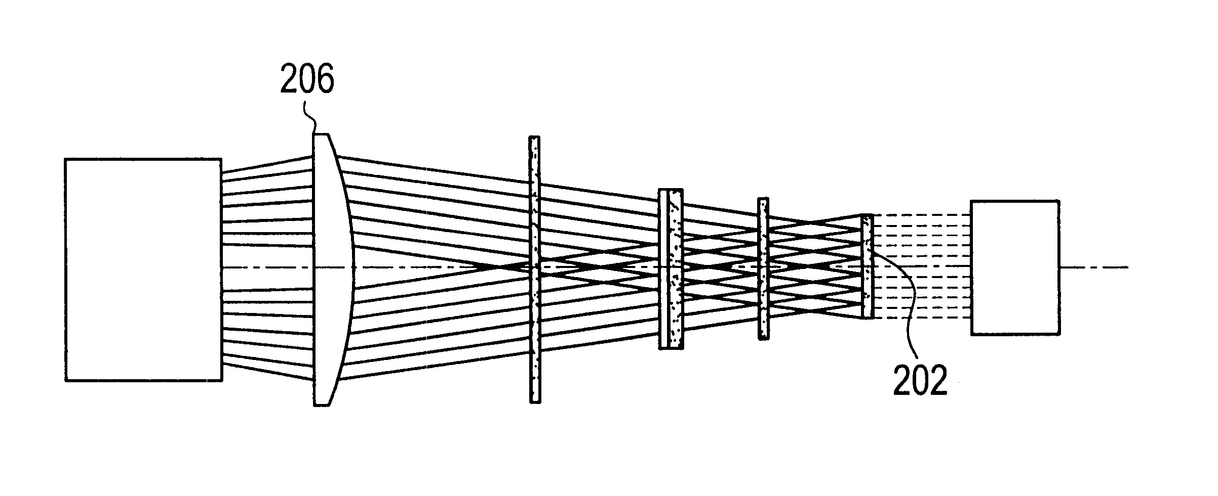
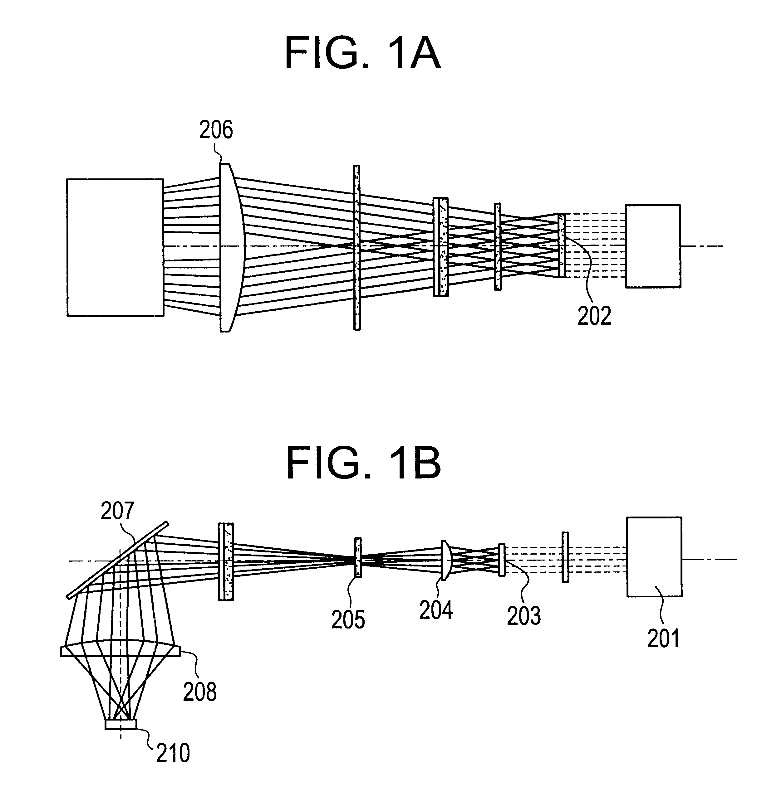
In the embodiment 1, the pitch d of the interference fringes when the arrangement of the optical system shown in FIG. 1 is adopted can be easily obtained through calculation. In this embodiment, the calculation method will be described with reference to FIGS. 11 and 12.
First, such a state is supposed that the divided lenses of the cylindrical lens group 206 are not shifted from each other. For convenience, the cylindrical lens group 206 in this state will be referred to as a cylindrical lens 1206.
The optical system shown in FIG. 11 may be regarded as showing the sections of the cylindrical lens group 202 shown in FIG. 1 and the cylindrical lens 1206.
In the case where the arrangement of the optical system of FIG. 11 is adopted, beams synthesized by the cylindrical lens 1206 may be said plane waves, respectively.
In this case, a light flux of laser light incident on the cylindrical lens 1206 through two lenses 1201 adjacent to the center lens, among the lenses constituting the cylindri...
PUM
Abstract
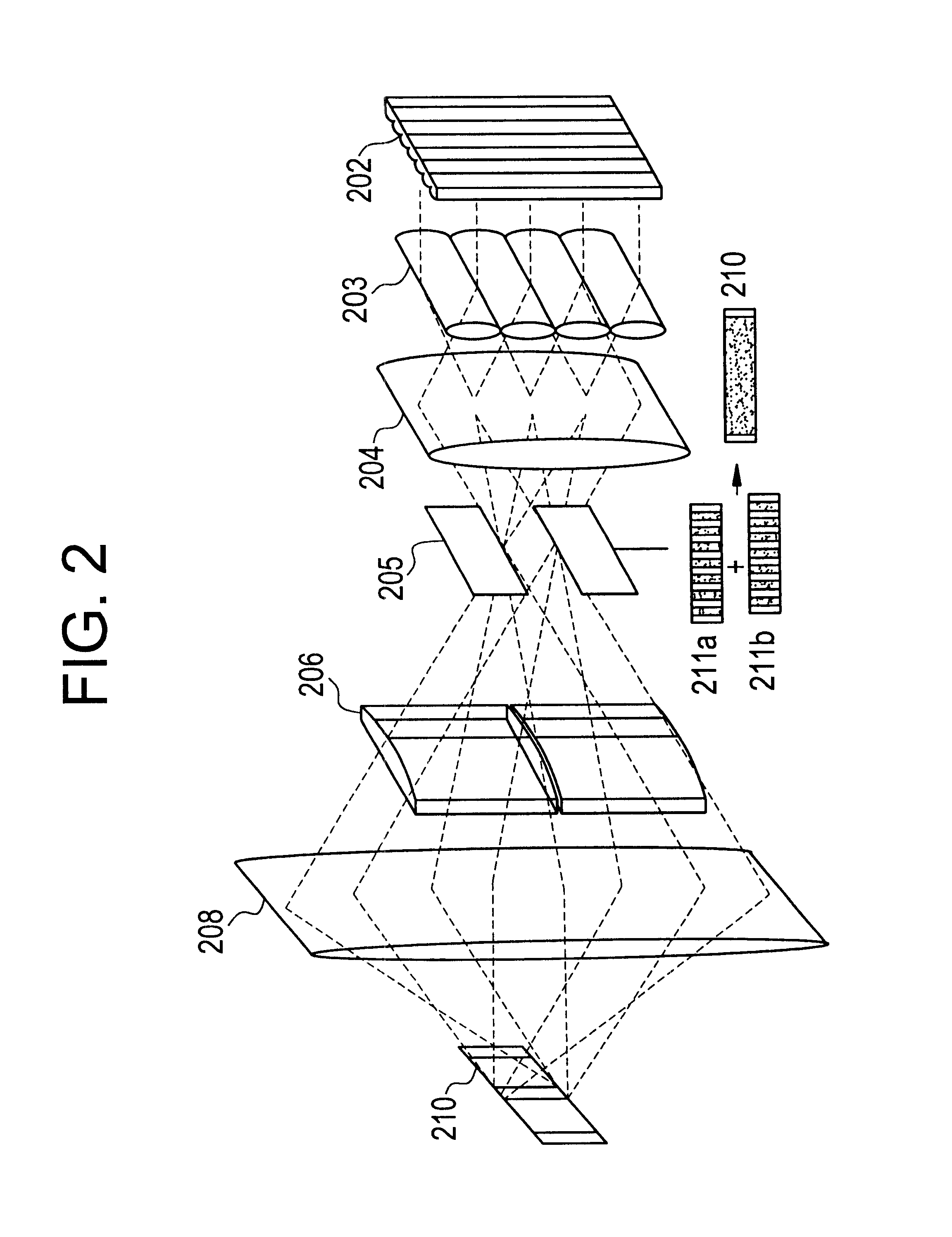
There is provided a beam homogenizer which can unify the energy distribution of a linear laser beam in a longitudinal direction. In the beam homogenizer including cylindrical lens groups for dividing a beam, and a cylindrical lens and a cylindrical lens group for condensing the divided beams, the phases, in the longitudinal direction, of linear beams passing through individual cylindrical lenses of the cylindrical lens group for condensing the divided beams are shifted, and then, the beams are synthesized, so that the intensity of interference fringes of the linear beam on a surface to be irradiated is made uniform.
Description
1. Field of the InventionThe present invention relates to a technique for uniformly irradiating a laser beam to a large area. In addition, the invention relates to its application.2. Description of the Related ArtIn recent years, a wide research has been made on a technique for carrying out a laser annealing to an amorphous semiconductor film or a crystalline semiconductor film (semiconductor film having crystallinity, such as polycrystal or microcrystal, not single crystal), that is, a non-single crystalsemiconductor film formed on an insulating substrate of glass or the like to crystallize it or to improve its crystallinity. A silicon film is often used as the above semiconductor film.As compared with a quartz substrate which has been hitherto often used, a glass substrate has such merits that it is inexpensive and is rich in workability, and a large substrate can be easily formed. This is the reason why the foregoing research has been carried out. Besides, the reason why a laser...
Claims
Application Information
Patent Timeline
Application Date:The date an application was filed.
Publication Date:The date a patent or application was officially published.
First Publication Date:The earliest publication date of a patent with the same application number.
Issue Date:Publication date of the patent grant document.
PCT Entry Date:The Entry date of PCT National Phase.
Estimated Expiry Date:The statutory expiry date of a patent right according to the Patent Law, and it is the longest term of protection that the patent right can achieve without the termination of the patent right due to other reasons(Term extension factor has been taken into account ).
Invalid Date:Actual expiry date is based on effective date or publication date of legal transaction data of invalid patent.

