Oil separation device for internal combustion engine

a technology of oil separation device and internal combustion engine, which is applied in the direction of engine lubrication, charge feed system, non-fuel substance addition to fuel, etc., can solve the problem of limiting the improvement of oil separation performance, and achieve the effect of improving oil separation performan

Active Publication Date: 2016-09-15
HONDA MOTOR CO LTD
View PDF4 Cites 40 Cited by
  • Summary
  • Abstract
  • Description
  • Claims
  • Application Information

AI Technical Summary

Benefits of technology

[0043]The oil separation device for an internal combustion engi...

Problems solved by technology

However, these approaches increase the flow resistance at the same time, and the resulting reduction...

Method used


Image

  • Oil separation device for internal combustion engine
  • Oil separation device for internal combustion engine
  • Oil separation device for internal combustion engine

Examples


first embodiment

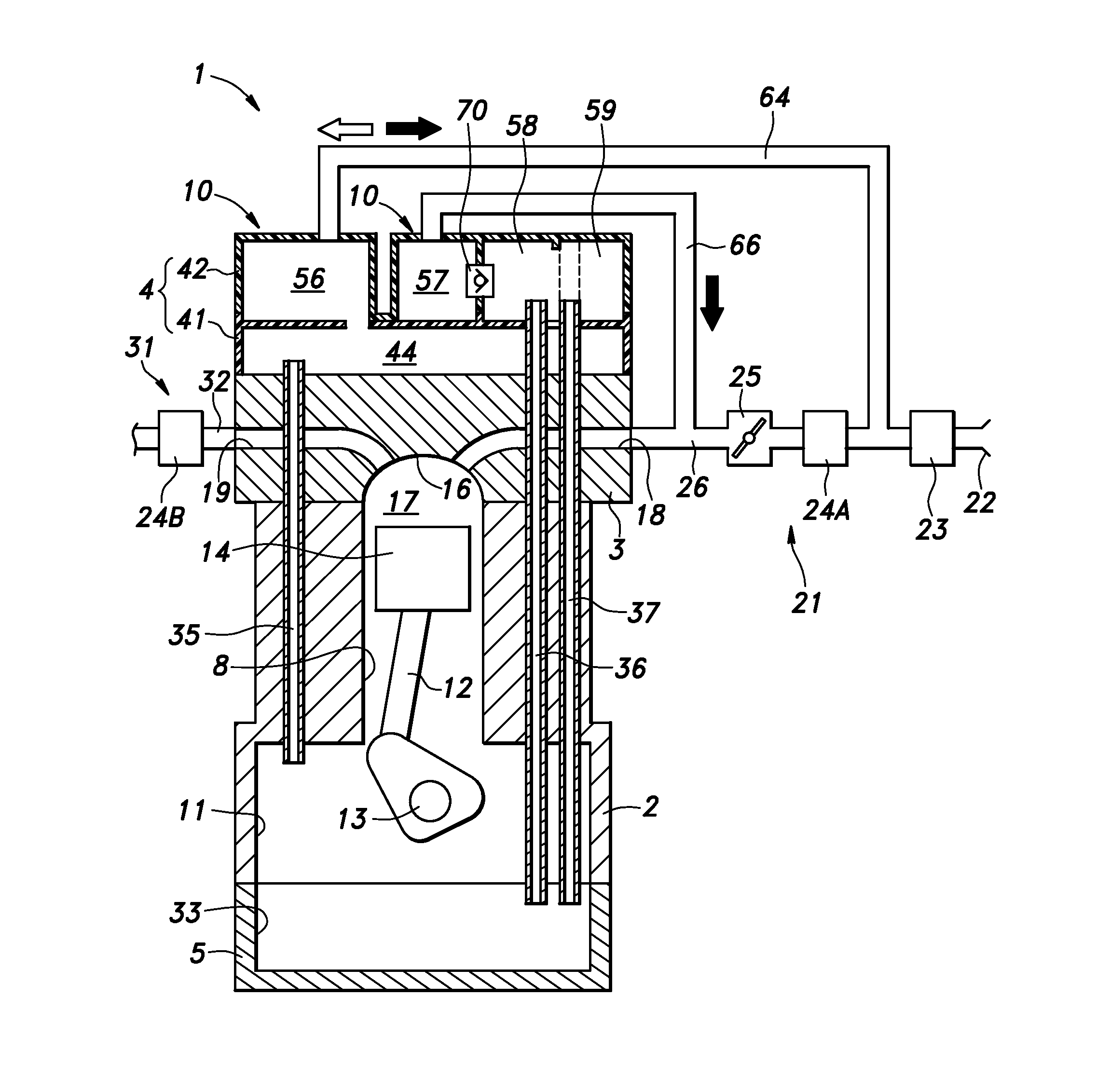
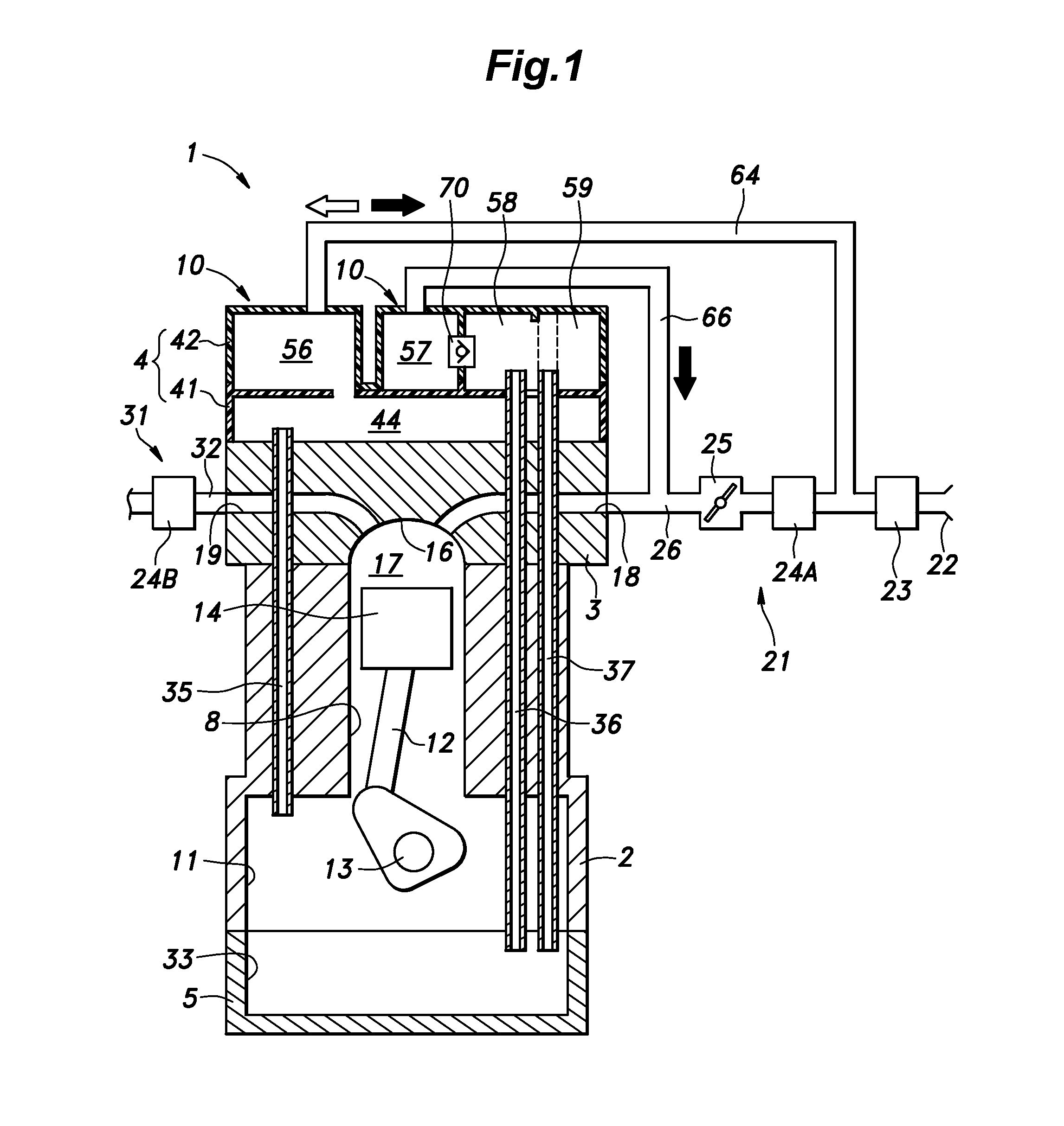
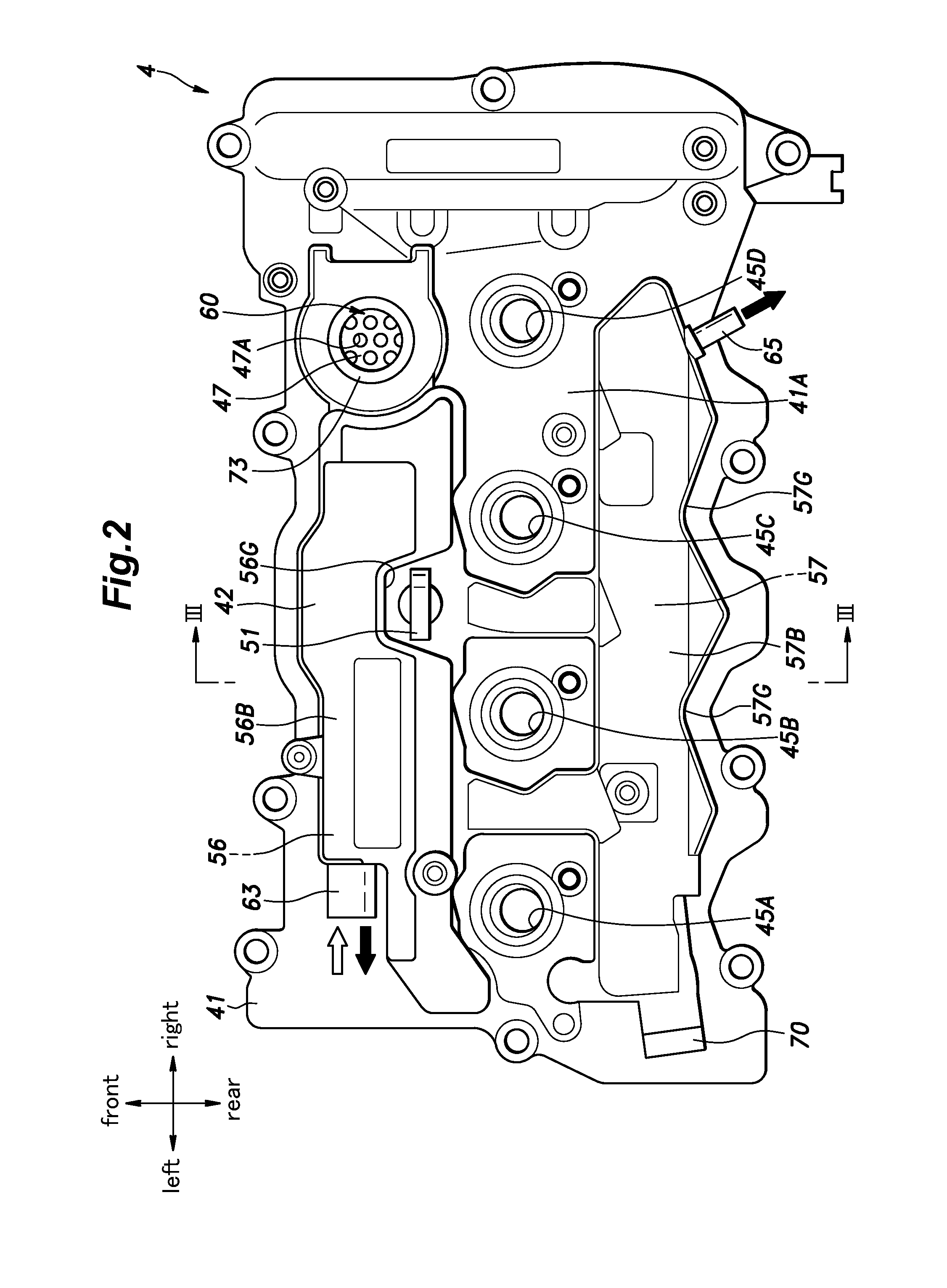
[0069]The internal combustion engine of the first embodiment consists of an in line, four-cylinder reciprocating engine. As shown in FIG. 1, the engine 1 includes a cylinder block 2, a cylinder head 3 attached to the upper part of the cylinder block 2, a head cover 4 attached to an upper part of the cylinder head 3 and an oil pan 5 attached to a lower part of the cylinder block 2. The head cover 4 is provided with a pair of oil separation devices 10 for removing oil from gas circulating therein.

[0070]The cylinder block 2 defines four cylinders 8 provided with axial center lines which are mutually parallel to one another and disposed in series on a common hypothetical plane. The direction along which the cylinders are disposed are called as a cylinder row direction, and the direction perpendicular to both the cylinder row direction and the lateral direction is called as a fore and aft direction. The cylinders 8 are referred to as the first, second, third and fourth cylinders from the...

second embodiment

[0128]In the second embodiment, the internal combustion engine of the present invention consists of an automotive, in-line, four-cylinder engine (L4 engine). The directions mentioned in the following description are based on the directions of the vehicle shown in FIG. 10.

[0129]In the second embodiment, the vertical direction corresponds to the plumb vertical direction of the engine when installed on a vehicle body. The first end of the cylinder row corresponds to the left side of the vehicle on which the engine is mounted, and the second end of the engine corresponds to the right side of the vehicle on which the engine is mounted or the side on which the chain case of the engine is provided. The upper side corresponds to the side where the head cover is provided, and the lower side corresponds to the side where the oil pan of the engine is provided. The front side corresponds to the side where the exhaust camshaft is provided, and the rear side corresponds to the side where the inta...


PUM


Abstract

To improve the oil separation performance in an oil separation device for an internal combustion engine. The oil separation device (10) comprises a gas liquid separation passage (56) internally defined by a lower wall, an upper wall and a pair of side walls, and extending in a horizontal direction, a gas inlet (54) and a gas outlet (63) provided on either end of the gas liquid separation passage, a plurality of lower partition walls (56H) projecting upward from the lower wall, and a plurality of upper partition walls (56J) projecting downward from the upper wall. The lower partition walls and the upper partition wall are tilted with respective the length wise direction in plan view so as to define a spiral passage. The lower wall is inclined with respect to a horizontal plane such that an upstream part of the lower wall is lower than a downstream part of the lower wall with respect to a direction of the swirl flow.

Description

TECHNICAL FIELD[0001]The present invention relates to an oil separation device (breather system) for an internal combustion engine, and in particular to an oil separation device for separating oil mist from blow-by gas.BACKGROUND ART[0002]In the field of internal combustion engines, it is known to provide an oil separation device in a blow-by passage for returning the blow-by gas in a crankcase chamber back to an intake system. For instance, in the arrangements disclosed in Patent Documents 1 and 2, a head cover formed by combining a plurality of members is internally provided with a gas liquid separation chamber in which a plurality of baffle plates are positioned. The blow-by gas containing oil mist changes the flow direction thereof by colliding with the baffle plates as the blow-by gas travels from the inlet to the outlet of the gas liquid separation chamber. When the blow-by gas changes the flow direction thereof, the oil contained in the blow-by gas is caused to adhere to the ...

Claims


Application Information

Patent Timeline
IPC IPC(8): F01M13/04F02M25/06
CPCF02M25/06F01M13/04F01M13/0416F01M2013/0461F01M13/022F01M2011/023Y02T10/12
Inventor FUJII, TAKESHISHIGEMOTO, KAZUNARIODO, MAYUKAKASAJIMA, YUYAKOMATSU, HIROTAKASAITO, JUNYANAKANO, KOUJIMARUYAMA, SEIMATSUSHIRO, YOSHIKI
Owner HONDA MOTOR CO LTD
Why Eureka
Try Eureka